- Software
-
 Questions

Problem using Current CIN sensors
Hi,
I need some help.
I have trouble using CIN sensors.
I have no problem with any others sensor types, but with almost all current sensors (4-20mA), I get an error with the signal (24mA) after some use.
But not all the time.
For exemple, here I have some undesired spikes while measuring.
Spikes are very short so I can't read +24mA in IQAN but I think if there was longer, I would have 24mA, so more than my scaled value at 20mA
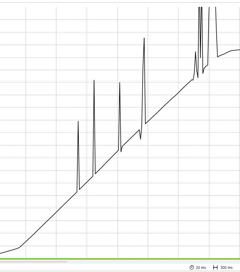
For this exemple, the value come back to a good value quickly, but sometime it stays in error ~= 24mA
Have you ever had similar problem ?
Do you have some advises ?
I can't use Vref+5V because my sensors can be supplyed between 8-32Vdc.
The sensors used are made with 3 wires : +24V / 0V / Signal
So the wire 0V is connected to the 0V of the battery, but on every machine, the 0V of the battery is conencted to the chassis of the machine.
Iin the manual it is recommanded to do not connect the 0V to the chassis. It's not possible on mobile machine.

So we tried to connect the 0V to the VREF- but it's doesn't work obviously.
Is there a way to have a VREF for sensors that supply about 10Vdc ?
Hope someone has some experiences that can help us to understand this problem with current sensors !
Customer support service by UserEcho

We are using several 4-20mA sensors but they are not connected the same way as yours.
Our sensors just has two pins and we power the sensors with 12VDC on one pin and connect the other pin to the CIN input.
So the sensor is effectively grounded through the CIN input, which is fine since it output current and the computer input has low input resistance.
We only ever had one issue with this setup with a particular sensor which had unusual characteristics.
While most sensors would work down til the minimum stated operating voltage and then gradually produce an non linear output signal, this particular sensor would instead suddenly cut the output signal below a certain voltage.
What made it worse was that the threshold voltage, where the sensor would cut, increased with increased output current.
This meant that the sensor in fact needed higher supply voltage that the minimum stated voltage if the sensor output current was in the higher end of the scale.
This meant the fault would only trigger under certain conditions which made it rather tricky to find and understand..