- Hardware
-
 Questions

IQAN-DG Display failure
Hello admins & all,
I bounced into this forum while searching for information pertaining to IQAN-DG instrument.
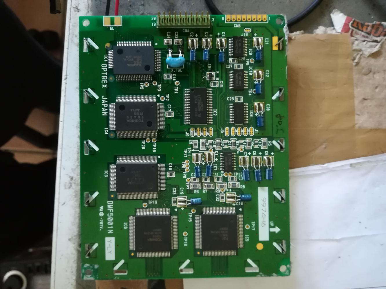
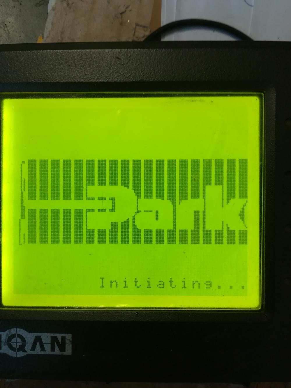
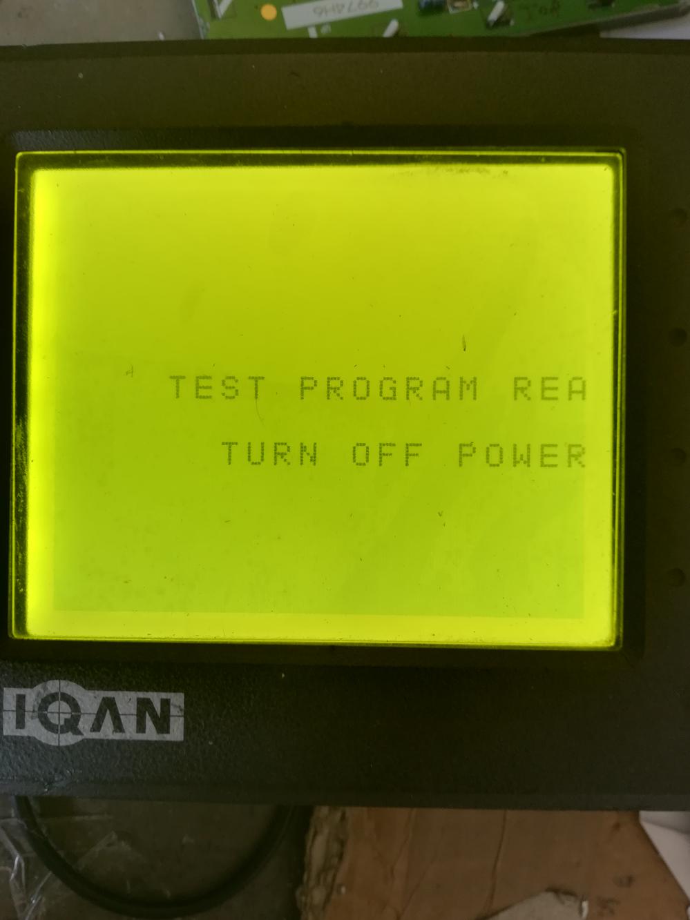
My problem is that the display is distorted or rather damaged. On the printed circuit board, it stateds DMF5001NY-LY Org_DMF5001NY-LY.jpg . I managed to acquired a new display unit DMF5001NY-LY-ATE-BBN . After installing, this display unit seems not compatible! The resolution of the text seems
weird, enlarged, cut-off and shifted to the right side Text_res1.jpg Text_res2.jpg.
As i am lack of technical information regarding the screen resolution, i am lost here. I assume this is a resolution problem with the new display unit.
Any information, help or solution to this problem is greatly appreciated.
Regards
David
Customer support service by UserEcho

Hello David.
The only two options i can give you is to send the DG in to Parker for repair or contact the OEM for the machine it is suppose to be installed on and ask if they still have a replacement DG.
Get in contact with your local Parker sales company to get further information about how to proceed with a repair.
Hi David
Are you still working on this problem?
From the pictures is looks like your font mode is wrong 8x8 and not 6x8.
Normaly you can set this with some jumpers at the back of the display.
Do you have a picture from the back of the new display.
Best regards
Søren
I don't know if this was solved by the original poster, but I encountered the same issue when replacing the display in an IQAN-DG. I ordered the display from the link below:
https://www.elecok.com/dmf5001ny-ly-aie-4-7-stn-lcd-panel-for-optrex-replacement.html
To make it work properly, I had to do the following modifications on the new display unit:
1. Putting the display in 6*8 font mode:
- Move 0 ohm resistor from FSL to FSH
2. Adapt for external LED drive:
- Remove VBL, R27 and R29
- Change R14 from 15 ohm to 0 ohm
- Solder cable from original display, the wire from A to LED+, from B to LED-
A follow up on my last post. I changed the display on three IQAN DG units, and they have all been working fine until this week, when one of them suddenly got a very bad contrast. I had noticed that it was not possible to change the contrast from the menu on the new displays, but it was very good, so I didn't bother much about that.
But now I had to look more into what had happened. It turns out that the new display modules have their own circuitry for creating the negative voltage that is required for the contrast setting, so the voltage that comes from the IQAN DG board is not used at all. It was this circuitry that now failed on one of the units. Don't know if it is a generic fault on these modules, or why this happened.
But here's how to modify the display module so that it will use the contrast setting from the IQAN DG board instead:
1. Remove Q1 (in the image also VADJ is removed, but I don't think that is necessary).
2. Add a wire from one of the pads of R6, going to pin 5 on the main connector header.
3. Fixate the wire with some glue.
4. When installing the display in a machine, you'll probably not see anything before you have to set the contrast. This is made in the display settings, in the Huddig machine that I was testing this in it was accessed by pressing MENU, RIGHT, second soft menu button from the top twice, DOWN multiple times to lower the contrast setting until the image appears.
In this machine, the old setting was 56%, and I had to lower it down to about 29% before getting an image.
abctay.com .It can solve your problem. I see they have a lot of panel sales
Can someone help with same issues here with replacement LCD module.
Mine have no jumpers like OP. Any other settings advices are appreciated.
I can't find oem replacement. Parker is redirecting me to other dealers, who does not know what they are doing.
Hi!
It looks like the font setting on your module is made through JP1 and JP2, connected to FS0 and FS1 pins on the Toshiba LCD controller. The datasheet can be found here:
https://www.alldatasheet.com/datasheet-pdf/pdf/215091/TOSHIBA/T6963CFG.html
On my module FS0 was directly connected to GND, and only FS1 was available through the FSL and FSH resistors. If your display is currently in 8*8 font mode that means that both JP1 and JP2 are connected to GND, which would mean that to put it in 6*8 font mode you should change JP2 to Vcc. I would assume that if you remove the solder blob om JP2 you should find two pads beneath it. Make sure that there's no connection between them anymore, and solder the center pad to the pad to the right instead.
Was the red and black wires already assembled when you got the module? If so I suppose that it is already prepared for external backlight control, and that it should be possible to just connect the original wires from the IQAN DG there.
My module had a built-in backlight control, which meant that it wasn't possible to change from the IQAN system, so therefore I had to make the extra changes to the module to make it controllable from the menu system.
I think it should be possible to verify that the backlight is working by connecting the cables to a lab power supply operating in constant current mode, but I don't remember how much current it needed to light up (depends on the internal arrangement of the LEDs in the panel).
I don't know if there's anything else that you need to do before it will work, but I hope that this could give some help.
Hopefully you don't have to do anything about the contrast setting as I had to do on the one that failed.
Thank you a lot. I have an electronics repair shop, thousands boards went thru my fingers, but when my mind got tired i just cant think properly and thank god people like you exist to open my eyes!
Gonna try and test tomorrow.