Parker XA2 DOUT voltage pulsing?
I have a system with a MD3 controlling a XA2 with several relays and solenoids controlled by DOUT channels when certain unrelated circuits are activated the DOUT power pulses continuously as long as the other circuit is activated. before and after using this other circuit that does not run through the XA2 the unit operates as normal.
what would cause these outputs to pulse? Their status even changes true/false in the MD3 monitor screen as they pulse. grounding has been confirmed and checked at different locations.

Vin reading errors on XA2
I was forced to change my Pressure Transmitter due to the world-wide supply chain mess.
One that I could get my hands on that looks like it should be able to do the task is the IFM PU1700. I get wild reading from it when read by the XA2, but when I read it with a multi-meter, the voltages are right were I would expect them to be.
Any ideas of what to do? Is there a way to determine what will work and what wont without buying, waiting, and trying?

XC-43 Modules Leakage Current/Voltage
The Leakage Current/Voltage from the Digital Outs make it difficult to control LED's and Audible Devices without using a relay/resistor/other. The Leakage Current/Voltage is also making it difficult if the Digital Outs are read by other electronic devices (off is not off). How does Parker recommend interfacing with these devices using the new XC-43/series modules? Adding external devices to these circuits is making the XC-43 modules not very convenient.
XC43 Flashing normal (yellow) with CAN-BUS no contact error on master module and in IQANdesign.
I've got two XC43's on a machine. One on CAN-BUS-A & the other on CAN-BUS-B. Both modules are flashing yellow normal operation but the master module says A-BUS no contact & B-Bus no contact. When I run the program in IQANdesign connected to the machine, I also see no contact on both modules.
Why are the two XC43 modules flashing the normal operation flash code and not the CAN error/no contact error flash code?

XC44 HS+LS Overcurrent Update
I am still unable to reply to previous posts with the same error being reported as before when I attempt..
In reply to Gustav's comment on this post: XC44 HS+LS Overcurrent Follow Up / Hardware / IQAN
"Ok, the disabling of the function group explain at least a part of the behavior you see.
When disabling the FG, the DOUT deactivate. Diagnostics is still running, so when disabled all checks for output off are running. In IQANdesign you will only see channel status disabled though.
At what events do you disable? Only before cutting the highside externaly?
Or also during normal deactivation of the output?"
The function group is only disabled on Estop. Before an estop event the output functioned as normal, the estop being triggered starts the overcurrent issue.
Original post: XC44 HS+LS Overcurrent / Hardware / IQAN
XC43 COUT Open Load Threshold
What is the XC43 COUT open load threshold when the COUT is off?

DOUT error code flash on XC23 when output is disabled in IQANdesign
We have an application which has an optional function group containing a DOUT on an XC23 module. This function group is enabled or disabled using a digital parameter. With the function group disabled we get the output grey and 'disabled' state when measuring with IQAN Design, which is correct:
We also have no errors on screen stating open load (we have nothing connected to output because this machine has not got the optional extra fitted). XC23 module has error code flash of DOUT, I suspect open load. Its not logging any errors or open loads in any logs within master module, viewing state of the module using IQAN Run I also get 'OK' and no errors on status screen just the LED status is showing incorrect state directly on the module:
https://www.dropbox.com/s/gt9sga2eys10gg4/VID_20210720_101414.3gp?dl=0
If I delete the output from IQAN Design the error flash on the module disappears and it goes a steady amber flash, no errors.
Has this been fixed in a newer version? IQAN Design 5.06, MD4-5 M19 and XC23.

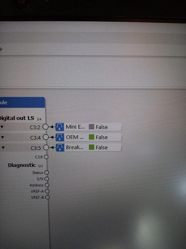
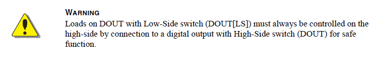
XC10 DOUT(LS)
Hi everyone,
I have been working on a quite complex system. When using XC10 all relay coils (or valve solenoids) controlled by DOUT(LS) have been powered from +BAT and it has been working fine. However checking program, for no reason, have found in the the Instruction book that one or more DOUT should be used to power these coils or solenoids. Is there any risk with what I am doing ? I have checked that for MC43 and MD4, that I have been using on the same system, it is allowed to use +BAT for power. I can of course do it by book but the program would become a little bit awkward and messy.
Any comments will be much appreciated
Richard Kowalczyk
RKad Engineering
Australia
In the XC10 instruction book

XA2 VREF Failure Effects
This is a two part question regarding the criticality of VREFs for IQAN Modules. We use an MD4 and XA2 in our system. On the XA2, we use VREF to support a three axis joystick and one pressure transducer (4 VINs).
We received a report from the field that a short circuit between VREF and ground caused the XA2 module to fail completely resulting in "I/O No Contact" IQAN Error Message on the MD4.
Is this a typical or expected failure mode for an XA2 with a damaged 5V reference voltage regulator? Or is it more likely there was a mis-diagnosis from the field? I can't think of a way to validate this without destroying an otherwise healthy XA2.
Would this also be the case in an MC42?

XC43 PWM Output voltage jumping from 6V to battery voltage randomly
I'm having an issue where the PWM outputs jump in voltage to battery voltage seemingly randomly and with no change in the displayed output on IQAN run. Anyone know what is going on?
Customer support service by UserEcho