- Software
- IQAN toolbox for Simulink
-
 Questions

Exporting issue
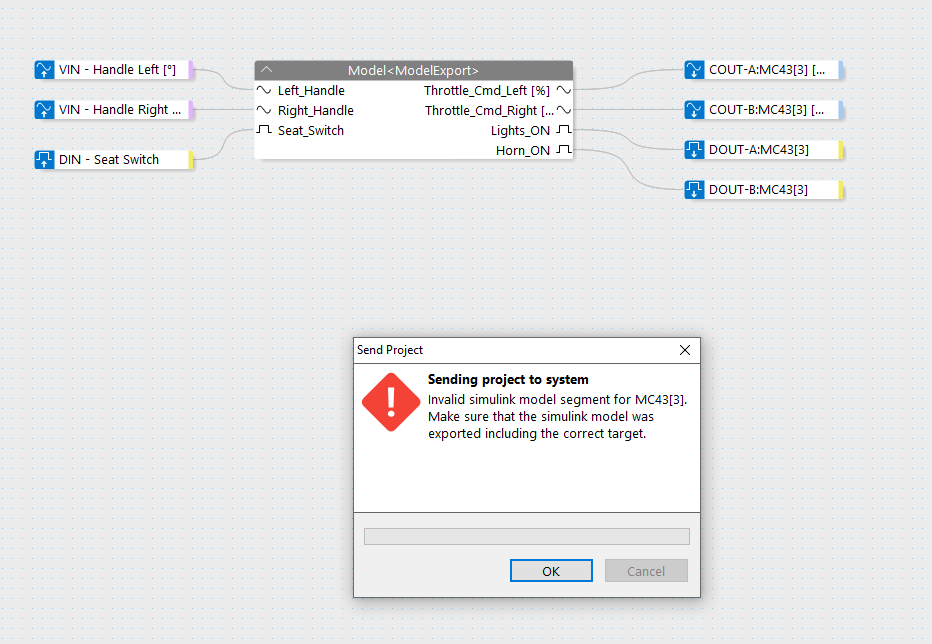
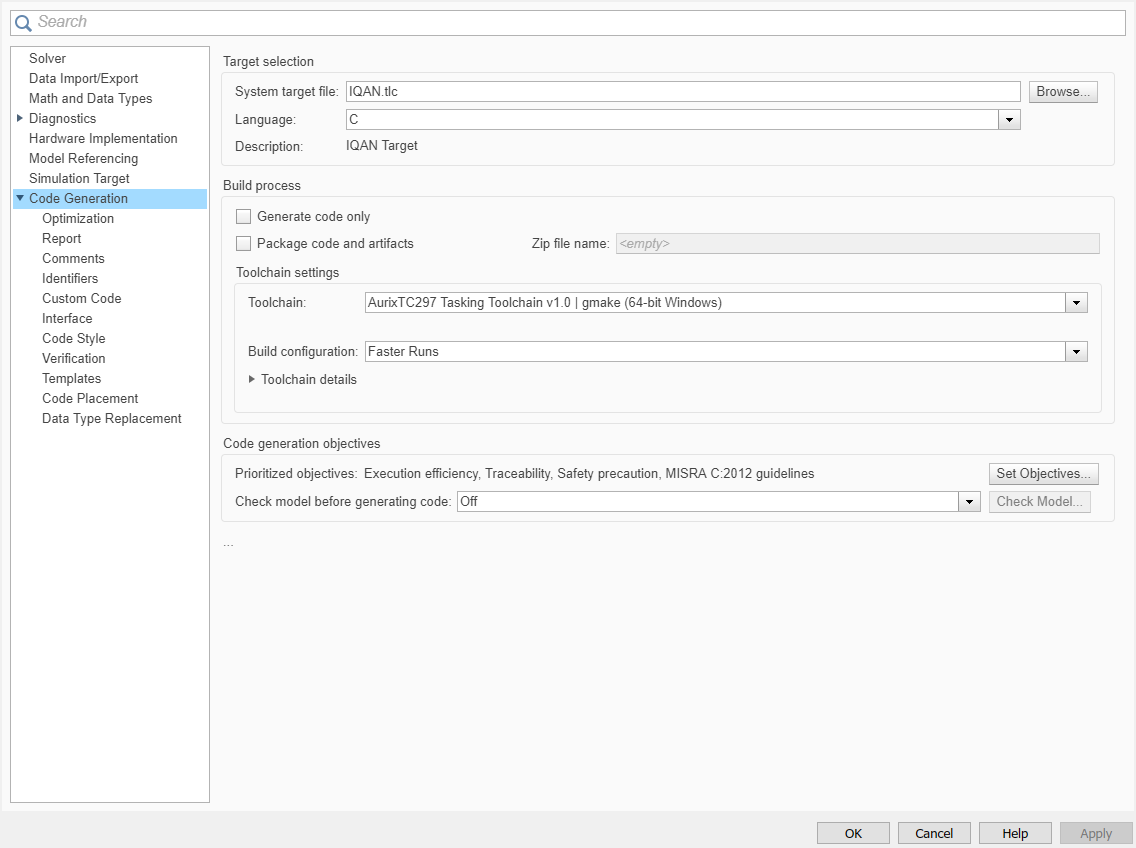
I am seeing the following error with Simulink export (the config file is attached). Can you please tell me how I can direct my config to generate code specifically for MC43? I am connected to MC43 through a Kvaser Leaf 2.

Answer

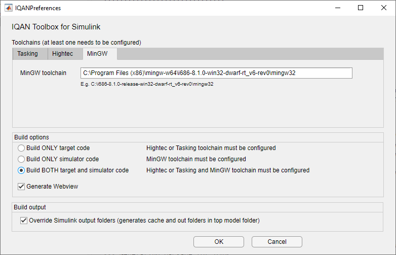
The IQAN preferences menu should normally be set to build both target and simulator code.
If it is set to only build simulator code the code will run in IQANsimulate on the PC, but cannot run on a physical IQAN-MC4x hardware (the target)
I think this could be the issue. I will check on Monday when holiday ends and update you. Thank you.
Yes, that solved it. Thank you.
I can now successfully transfer the code from IQANDesign to the MC43 controller. It seems I have to use the Hightec toolchain instead of Taskin as the latter requires a license to complete the code generation.
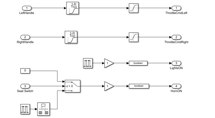
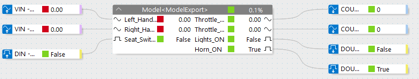
When I use Simulation, I can see that the logic is working as expected (see below). I intentionally did not resolve the input error to match what I have in the controller. But the two digital outs are working as expected (switching between True and False). The code inside of the Simulink block is simple as below.
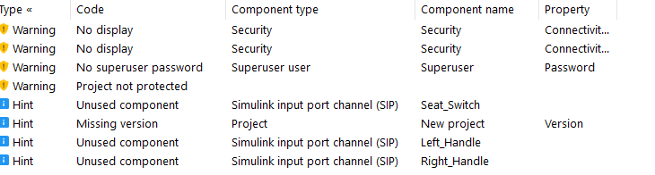
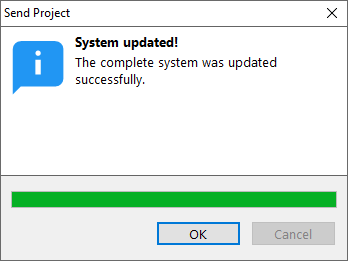
So now, when I transferred the code into the controller, it successfully completes it (I ignored some warnings as shown below).
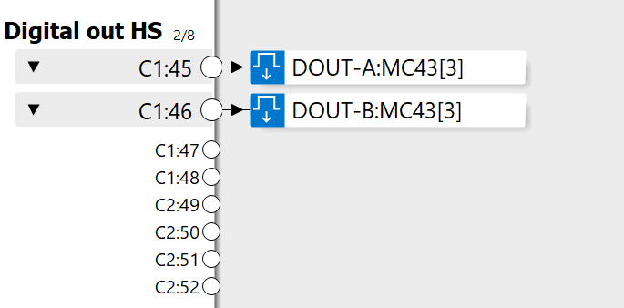
The digital outs are pin 45 and 46. So, I tried to measure these two pin voltages through a multimeter. I used the same ground as the supply (multimeter signal pin connected to Pin 45 and GND is connected to supply GND).
But I am always seeing 19.84 V (supply is 19.89V). Seems like no matter what I do, all the digital pins (I also checked Pin 47) are always high. The controller LED is flashing to indicate the 'input error' similar to what I have in Simulation (I have nothing connected in the inputs). Is there something I am missing here?
Thanks for your help in advance.

On those DOUT you have a leakage in OFF state that is <2mA, it is this that you are measuring with your multimeter.
But if you have something connected to the DOUT an measure you should not see anything in the off state.
I am not probably aware of familiar with the term 'OFF- State'. Can you please refer me to the documentation for further reading?
So, if I connect a 1kOhm resistance between the terminal (P45 and GND), will that considered as connected and I can see the fluctuation between 19V and 0V as intended?
Thanks.
Assume this is sorted out by now, but in case it isn't there is a similar question on leakage in this post on MC4x hardware:
https://forum.iqan.se/en/communities/5/topics/2461-pwm-to-control-small-load
Customer support service by UserEcho

The IQAN preferences menu should normally be set to build both target and simulator code.
If it is set to only build simulator code the code will run in IQANsimulate on the PC, but cannot run on a physical IQAN-MC4x hardware (the target)