- Software
- IQANdesign
-
 Questions

VIN High Error
I have a sensor I want to use that requires 18-36VDC for power, but outputs 0-10VDC for its analog signal (it is a laser distance sensor). The sensor does not limit its output, so there will always be the possibility of 10VDC being present on the VIN pin. Is there a way to keep the MD4 from displaying a 'high error'?
Answer

Hi Joe
I had the same problem, I use two methodes the first uses two resistors with the same resistance.
R1 between 10Vdc signal and Vin
R2 between Vin and Vref-
for R1 and R2 I use 4,7Kohm
For a more curate measurement i use a signal converter, these can convert al sorts of signals.
I use one from Wago
http://www.wago.com/wagoweb/documentation/857/eng_dat/d08570400_00000000_0en.pdf
regards Ed.
Thanks, Ed. I thought about this, but I was really hoping for a method that didn't cut the resolution in half, because I only care about half the distance measurement capability of the sensor. Do you know if this signal conditioner can be set to 0-5 V In and 0-5 V out to effectively clip the input signal?

Hi Joe,
This will not cut by half the resolution, it will only divide the voltage by 2.
for example, if you have a resolution of 1mV at 0-10V with your sensor, now you will have a resolution of 0.5mV at 0-5V for the same sensor, on the iQan input side.
That's it. It's a voltage divider, like a calculator.
You don't lost any digits.
Also, you can check for canbus signal reading adapter. take a look at www.axiomatic.com
I used them in the past, very simple and efficient.
Regards,
David
I would agree with you if it were not for the fact that I am only interested in half the original signal, so I would be effectively only be using 0-2.5V of the full signal after conditioning.

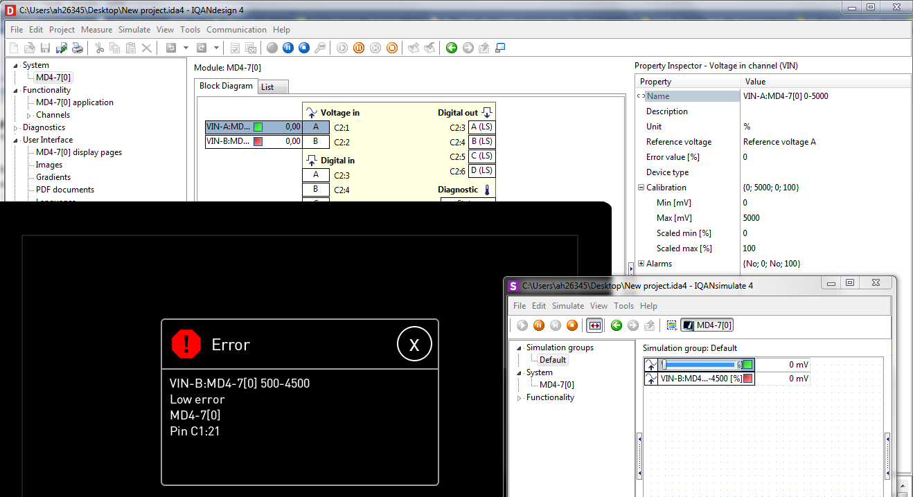
If your sensor signal is 0 to 5000mV then can avoid the high and low error warnings and failures by configuring your input with scaling from 0 mV to 5000 mV.
Quick example: Input A scaled with 0-5000mV, Input B with 500 to 4500, B shows Error, A still ok with 0 mV.
Hi Joe
If the signal conditioner wil chip the input I do not know.
In my case I could calibrate the sensor so it would have the full 0..10 vdc range output on the measured distance. So there is no los of resolution, like David aready mentioned.
Regards, Ed
In this case, leave the value as 0-10v from the sensor, use it at the half capacity to match the iQan inputs.
This will gives you an error if the sensor is out of range (>5v).
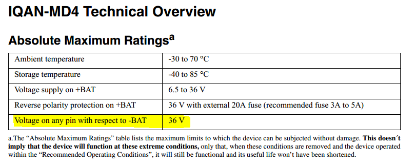
In my opinion, the input of the MD4 will survive at 10V.
If you don't expect to exceed the 5V value, it's a no brainer. You don't have to change anything.
David
There are instances when the sensor will be out of range when not in use, so I was looking for a way to ignore the high error in those instances.
Simply turn off the system alarm for the low/high value.
In the Alarms in the properties, if it's off, you will not have any message on the screen.
but in the iQanrun/design you will see a red square on this sensor when out of range.
You can do this. It's not an issue if you don't have to use the internal alarms managment of this specific input.
David
I am not getting an Alarm, I am getting an Error. The default for 'Alarm Low' and 'Alarm High' is 'No' and has not been changed.
In this case, you can use the same circuit as Ed show in a previous message, but replace the last resistor by a Zener diode who will limit the voltage to 5V.
Check the maximum output your sensor can deliver to match the first resistor value to avoid any failure.
the zener will limit the voltage to a specific setpoint depending which one you choose.
see this link : http://www.ti.com/lit/ds/symlink/lm136-5.0.pdf
but the best way still be an input module with canbus communication, this will avoid any confusion.
Check this link : http://www.axiomatic.com/distributed-control/1-universal-signal-input-can-controller/
It's a very good product, mobile design. It's also easy to use.
David
I have found a way around this. The error only appears when the max setting (mV) is less than 5000mV. I used the VIN (mV) adjustment to calibrate the distance measurement, therefore the error would appear. I now adjust the min and max values of a vector channel using function parameters. The distance measurement is calibrated and no error message appears even when the voltage at the VIN pin goes to 10V.
Thanks to everyone who responded to this and I hope you find my solution helpful.
Customer support service by UserEcho

I have found a way around this. The error only appears when the max setting (mV) is less than 5000mV. I used the VIN (mV) adjustment to calibrate the distance measurement, therefore the error would appear. I now adjust the min and max values of a vector channel using function parameters. The distance measurement is calibrated and no error message appears even when the voltage at the VIN pin goes to 10V.
Thanks to everyone who responded to this and I hope you find my solution helpful.