- Hardware
- Master modules
- MC4x
-
 Questions

PWM for controlling fan and coolant pump speed / schematic PWM signals
Hello everybody,
I'm working on a project, where i want to control the speed of a brushless SPAL fan and a BOSCH cooling pump via a PWM-Signal from a PARKER MC43.
However, I'm running into some issues with this.
1- First of all, I dont know how to wire the components. The fan und the pump, both have only 3 pins when it comes to PWM controlling. 24V + , 24V ground and the Sinal pin for PWM. On the MC43 i do have 2 pins per PWM signal. Could anybody show me how to wire those components? I added a unfinished schematic:
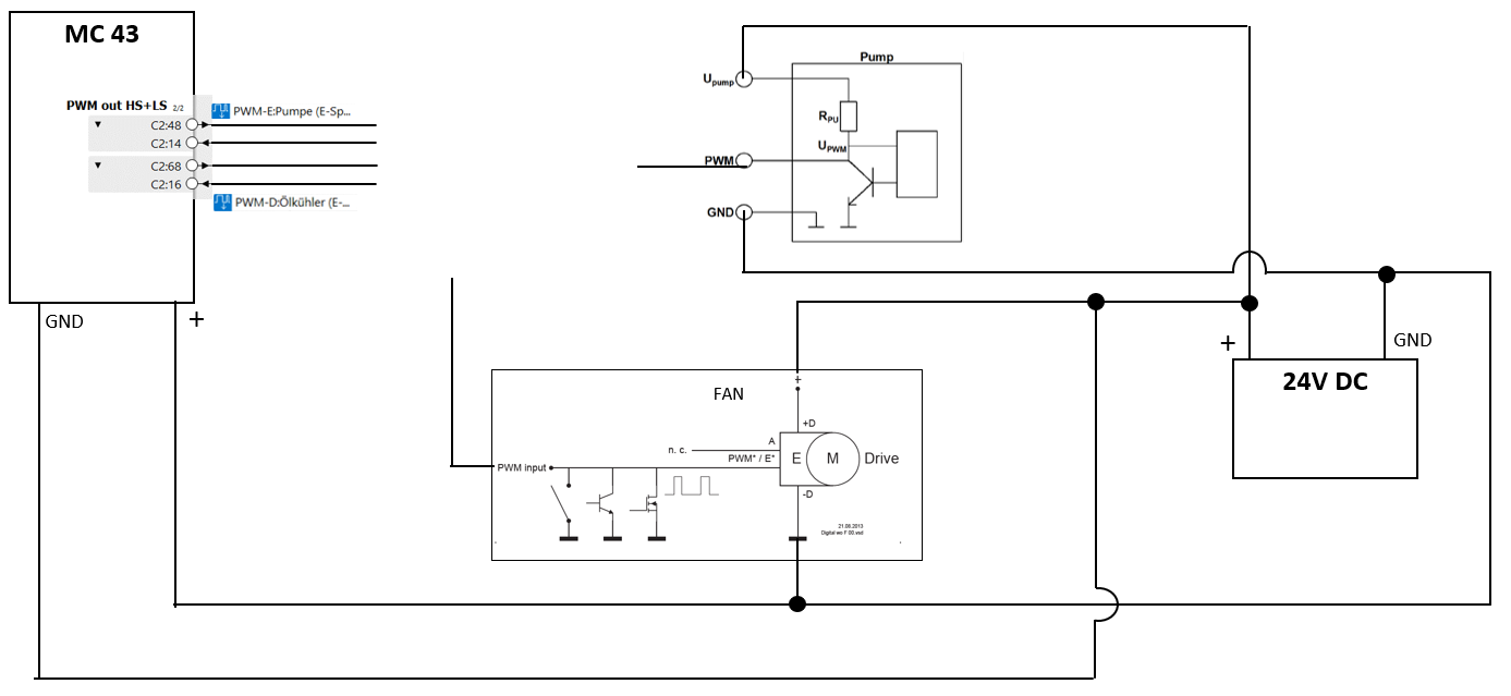
Maybe I'm missing something completly obvisous here but additions to not knowing how to wire these components, I don't understand what has to come on the PWM*/E* pin of the fan. From the picture it looks to me like this pin needs a PWM signal, wich is switched to ground. I'm not an electrical engineer but from what I understand, there is a difference between GND (-) and not having a actual potential difference. Like when something is on two pins connected to 24V DV there is no actual potential difference but there is no GND. Can anyone explaine what needs to be connected to the PWM*/E* pin of the fan?
2- The second point is, I found this threat on the Parker forum wich comes kind of close to some of my problems:
https://forum.iqan.se/en/communities/5/topics/588-pwm-as-control-signal
Where is written:
" You could use the PWM output on e.g. an XA2 or XC10 to do this, but there are a few limitations to think of The most important is the off-state leakage current on the highside driver. This is just as relevant for the case when one wants to use DOUT as a signal to another controller. If you do not pull the output to ground, you will see a voltage on the output pin that is close to +BAT level. The other will have some voltage threshold that you must be sure to be able to come below.
It is very probable that the PWM input on the other device have a pull-down resistor in the kOhm range. Then you will need to add an external pull-down resistor to load the signal. Which is tricky because this low resistance component will also have to cope with the power during the on-phase.
Another limitation you need to consider is the PWM out range. As the IQAN PWM outputs are primarily intended to drive valves, none of the outputs go all the way to 100% MR.
For modules that has undercurrent detection (like XC10), you might need to switch this off, depending on how much you load the output."
When it comes to the MC43 Module, are these problems still the same or has anything changed since that?
Because this Answer is around 5 Years old. Sorry if there are some obvious solutions to my problems, I'm still quite new in this.
Customer support service by UserEcho