Using dual crossed signals
The analog joysticks in the IQAN range, e.g. LST, LSL, LC5-X05 and LC6 all have dual crossed signals for each axis. The purpose of this additional signal is to reduce the risk of unintentional activation by having a second signal to compare with.
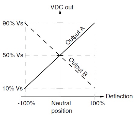
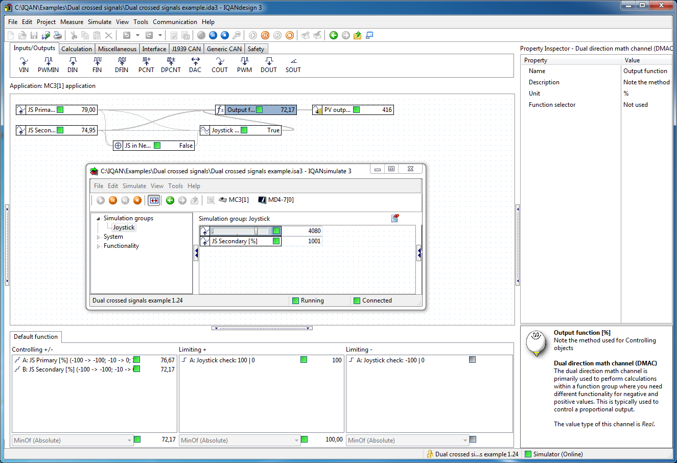
How the dual crossed signals are used can vary a lot. This article will guide you through an example that uses the MinOfAbs method for redundancy, the AAC channel for diagnostics and also for a start-up check.
Voltage input (VIN) scaling
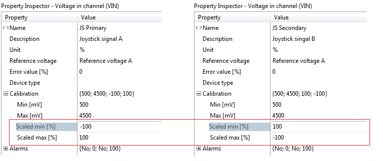 The two VIN channels are scaled so that the joystick deflection is measured from -100% to +100%, with 0% in the neutral position (2500 mV).
Min. 500 mV, corresponds to -100% on the primary signal, and +100% on the secondary.
Max, 4500 mV, corresponds to -100% on the primary signal, and +100% on the secondary.
Deadband with multi vector
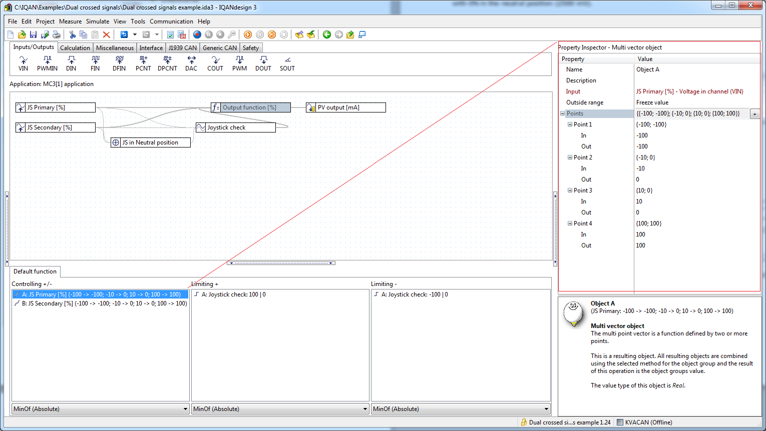
The easiest way to add a deadband for the two signals is to use one Multi vector object for each VIN,
with four points in the multi vector. A 10% deadband in each direction corresponds to +-200mV for the 500-4500mV joystick signals.
MinOfAbsolute Method for redundancy
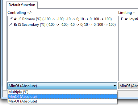
By selecting the method MinOfAbsolute for the controlling objects, the signal that gives the smallest command will be selected. Thus, both primary and secondary need give a signal outside of the deadband to give a command.
Analog Analog Analog Compare channel for diagnostics
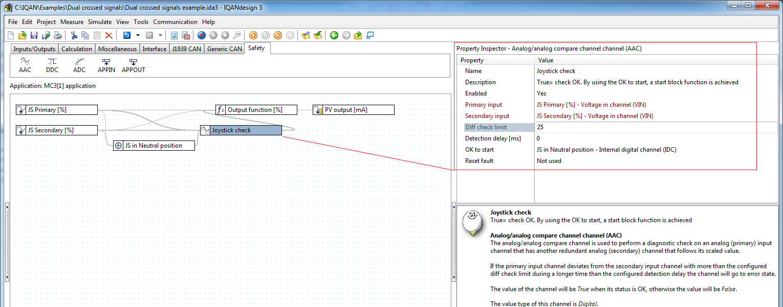
The two crossed signals should be compared to detect if the indicated joystick deflection differs too much between the signals. The easiest way to implement this is by using the Analog Analog Compare channel. This compares the scaled values. If the difference between Primary and Secondary input is larger than the Diff check limit, an error is triggered. A diff check limit of 25% is wide enough give margins against false triggering of the error detection for all IQAN joysticks. Since this allowed difference is greater than the 10% deadband, it is recommended to always check that both primary and secondary are outside of the deadband, for example with the MinOf absolute method shown above.
The value type of the AAC is digital. Use a Dual object in the Limiting+ and Limiting- to limit the output function to 0% when the check is not ok (false).
Startup and restart conditions with the AAC channel
At startup, or after fault has been detected, the AAC channel will stay in start block state until the OK to start channel is True. This can be used to check that the joystick is in neutral position first, before activating the output.
A comment about naming
Normally, it is wise to give channels with digital values names that indicate the condition when the channel is True. Following this logic, the AAC channel here should be named ‘joystick check OK’.
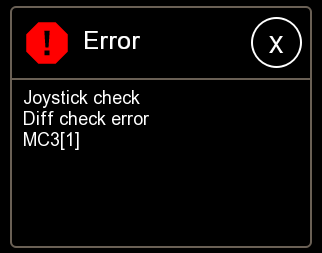
But in the case of the AAC channel, the automatic error message for a diff check error includes the channel name, this error message could be confusing if it said ‘joystick check OK’.
Example file in IQANdesign 3.14
Dual crossed signals example.ids3
When installing IQAN Creative Studio, you get a couple of other examples in one of the solution library files “Safe LST–LSL”, that installs under \Documents\IQAN Files\Solution Library\

How the dual crossed signals are used can vary a lot. This article will guide you through an example that uses the MinOfAbs method for redundancy, the AAC channel for diagnostics and also for a start-up check.

Voltage input (VIN) scaling
 The two VIN channels are scaled so that the joystick deflection is measured from -100% to +100%, with 0% in the neutral position (2500 mV).
 Min. 500 mV, corresponds to -100% on the primary signal, and +100% on the secondary.
Max, 4500 mV, corresponds to -100% on the primary signal, and +100% on the secondary.
Deadband with multi vector

The easiest way to add a deadband for the two signals is to use one Multi vector object for each VIN,
with four points in the multi vector. A 10% deadband in each direction corresponds to +-200mV for the 500-4500mV joystick signals.
MinOfAbsolute Method for redundancy

By selecting the method MinOfAbsolute for the controlling objects, the signal that gives the smallest command will be selected. Thus, both primary and secondary need give a signal outside of the deadband to give a command.
Analog Analog Analog Compare channel for diagnostics

The two crossed signals should be compared to detect if the indicated joystick deflection differs too much between the signals. The easiest way to implement this is by using the Analog Analog Compare channel. This compares the scaled values. If the difference between Primary and Secondary input is larger than the Diff check limit, an error is triggered. A diff check limit of 25% is wide enough give margins against false triggering of the error detection for all IQAN joysticks. Since this allowed difference is greater than the 10% deadband, it is recommended to always check that both primary and secondary are outside of the deadband, for example with the MinOf absolute method shown above.
The value type of the AAC is digital. Use a Dual object in the Limiting+ and Limiting- to limit the output function to 0% when the check is not ok (false).
Startup and restart conditions with the AAC channel
At startup, or after fault has been detected, the AAC channel will stay in start block state until the OK to start channel is True. This can be used to check that the joystick is in neutral position first, before activating the output.
A comment about naming
Normally, it is wise to give channels with digital values names that indicate the condition when the channel is True. Following this logic, the AAC channel here should be named ‘joystick check OK’.

But in the case of the AAC channel, the automatic error message for a diff check error includes the channel name, this error message could be confusing if it said ‘joystick check OK’.
Example file in IQANdesign 3.14
Dual crossed signals example.ids3
When installing IQAN Creative Studio, you get a couple of other examples in one of the solution library files “Safe LST–LSL”, that installs under \Documents\IQAN Files\Solution Library\
Customer support service by UserEcho
