
0
Completed
Problem with my system 1 MD4 and 2 MC3
Masia Jean-Baptiste 11 years ago
in Master modules / MC3
•
updated by Gustav Widén (System support) 10 years ago •
2
Hello everybody,
I have three problem in my system.
Can you help me ?
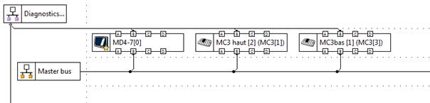
See above my configuration.
The first one:
In my system, when I supply the modules (1 MD4, 2 MC3), I don’t have any problem. When I power on the engine of the vehicule, sometimes the screen on MD4 is black and is blocked. No action is possible !!!!
The second:
When I power on my engine, sometimes I have an open load message in the MD4 on my Current out or Digital out on MC3. The wiring of the vehicule is good !!!!!
Do you have an idea on the two problems?
The third problem:
In my system I have a LED lights two colors (white and red) but I have three cable.
These leds work with low current ( less 200 milliamps ). We think that it will be possible with the “lowside” .
The first is the +VCC on the red light the second +VCC on the white light and the last is the ground for the two colors. One single LED works . When the red is on ( stop / brake ) the white is off . When he white is ON , the red is OFF.
How so you connects on the MC3 Digital Out?
I have three problem in my system.
Can you help me ?
See above my configuration.
The first one:
In my system, when I supply the modules (1 MD4, 2 MC3), I don’t have any problem. When I power on the engine of the vehicule, sometimes the screen on MD4 is black and is blocked. No action is possible !!!!
The second:
When I power on my engine, sometimes I have an open load message in the MD4 on my Current out or Digital out on MC3. The wiring of the vehicule is good !!!!!
Do you have an idea on the two problems?
The third problem:
In my system I have a LED lights two colors (white and red) but I have three cable.
These leds work with low current ( less 200 milliamps ). We think that it will be possible with the “lowside” .
The first is the +VCC on the red light the second +VCC on the white light and the last is the ground for the two colors. One single LED works . When the red is on ( stop / brake ) the white is off . When he white is ON , the red is OFF.
How so you connects on the MC3 Digital Out?
Customer support service by UserEcho

We have seen on the bench that you can get the MD4 display to become blank if supply voltage is ramped very slowly between 6 V to 9 V, but we don't see this behavior when running the normal ISO 7637-2 test pulse 4 cranking.
For the second issue, with the open load on COUT and DOUT during cranking, I have not seen this before. Are these outputs activated during cranking? If so, do they have to be on during cranking? What I am thinking is that the supply voltage may be insufficient to drive the loads during cranking, and therefore causing an undercurrent, that will be shown as an open load on the screen.
For the question about the 2-color 3-wire LED, I cannot think of a way to connect this to the MC3 DOUT without triggering an error. The MC3 DOUT:s are designed to work in a pair of one highside+one lowside for each load.
To control this 2-color LED, you would need two separate highsides.
For this reason, the low-side DOUT on the MD4 you have in the system cannot be used either.
One option if you don't need the safety certification on both MC3:s in the system could be to replace one of them with an MC31. On the MC31, you can control the 5 DOUT highsides and the 5 DOUT lowsides independently.
The IQAN-MD4 board has been updated to prevent the problem of display latchup when slowly ramping supply voltage between 6-9 V.
Implemented in production 2015-12-13