 Project Documentation Error
Good Morning,
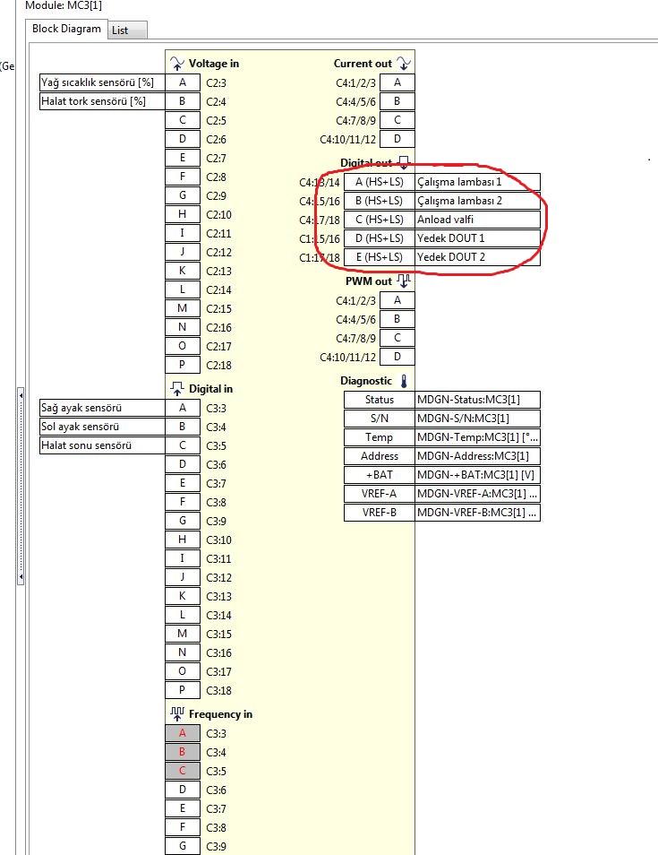
I have completed my first project in IQAN Design and while looking at the project documentation, I noticed what would seem to me like an error. Please see the attached screenshots on how the one pin list shows pin C1:4 under the Master Module as being ADDR-L and under the Gateway module it shows C1:4 as being CAN-H. What am I missing?


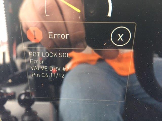
 MC31 Error 1:20 ??
Anyone have more information about the error 1:20 on a MC31 master module ?
I didn't find anything related to this error.

 Overload Errors when PWMOuts are Off
We have just updated from IQAN 3.19 to IQAN 4.06.
We are now seeing over load errors on several solenoids being controlled with PWM out signals.
The overloads only occur when the outputs are off. When they are on (90% Duty cycle) the errors go away.
I believe I remember reading something about circuit failure detection being active even when outputs are off as part of an IQAN 4 update.
Any recommendations on how this could be resolved?

 Measurement of current consumption on MC3 Vref
Is there a way of detecting how much current draw there is on the VREF supply on an MC3?
I have experimented with a SIL2 pressure transducer connected to an MD4 (don't have an MC3 to hand) and noticed that disconnecting the -VREF and leaving +5V supply and VIN signal wires connected to the controller will generate 2500mV signal into the MD4 VIN. This is not desirable as it simulates a pressure in the system which is not true. I can only imagine its how the internal electronic circuit is manufactured inside the transducer causing the false signal, but its not unique to one manufacture of pressure transducer. The current consumption of the sensor drops from 6mA to zero when the -VE is removed, wondered if this would be a good way to detect disconnected -VREF connection?
Aside from the method above or monitoring for a sudden change in VIN signal within the software, can anyone suggest any other solution to this issue?

 MC3 Output Error on Start Up
One of our field units is getting the an "Error" on start-up. It occurs on every startup.
After the error is cleared, everything is working fine. The solenoid(s) showing the error function with no issue.
In the past we have seen open load and overload output errors but not just a generic error message. We replaced the MC3 module and the problem was resolved.
Just curious on what this means? Thanks


MC3 Module Input Error
Hello,
I have a drill rig (Geoprobe 6712DT) which has an MC3 Module installed. Recently, the hydraulic pump would intermittently would stop building operating pressure, and the only workaround I can find is to bypass the MC3 Module and manually force the pump to build pressure. The Module is giving me a 1:2 error code, or "Input" error. Could someone help elaborate what this error could mean in the general sense? Any info would probably help with my troubleshooting. I'm guessing it could be something as simple as a loose wire, but I can't seem to find any so far.
The drill rig comes with the MC3 Module installed, and has worked fine up until recently. The manufacturer doesn't really provide any troubleshooting in regards to said module, so I'm kind of just winging it. The manual for the module tells me that it is an Input Error, but I'm not really sure what could be causing that.
Thanks in advance for anyone who can help me out. My apologies for being somewhat ignorant as to this thing... I'm just a humble driller.

 MC3 CAN, no contact and CAN error (bus off)
What is the difference between this two Error codes ?
Thank

 MC3 DOUT leakage current
we connect MC3 to LED working lamp with DOUT channel.

we connect MC3 to LED working lamp with DOUT channel. The Lamb current consumption is about 750mA. when its turn on.
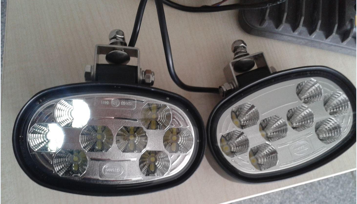
The Lamb turn on its fine no problem. but it works very lackluster When turn of the light. You can see photo on the bottom of the description.
Now, Turn off the lights. So on the photo left lamp connect the C4 DOUT, right lamp connect the C1 DOUT.
these problem are just C4 but C1 DOUT works fine. What causes it?
Thank you.


Problem with my system 1 MD4 and 2 MC3
I have three problem in my system.
Can you help me ?
See above my configuration.

The first one:
In my system, when I supply the modules (1 MD4, 2 MC3), I don’t have any problem. When I power on the engine of the vehicule, sometimes the screen on MD4 is black and is blocked. No action is possible !!!!
The second:
When I power on my engine, sometimes I have an open load message in the MD4 on my Current out or Digital out on MC3. The wiring of the vehicule is good !!!!!
Do you have an idea on the two problems?
The third problem:
In my system I have a LED lights two colors (white and red) but I have three cable.
These leds work with low current ( less 200 milliamps ). We think that it will be possible with the “lowside” .
The first is the +VCC on the red light the second +VCC on the white light and the last is the ground for the two colors. One single LED works . When the red is on ( stop / brake ) the white is off . When he white is ON , the red is OFF.
How so you connects on the MC3 Digital Out?

 MC31
MC31
Thanks!

Customer support service by UserEcho


