
 MD4 - GFOUT or JFOUT Assignment
Maybe I am missing something very simple, but I am struggling to understand how to receive an analog input on a XC23 connected to a MD4, convert it to a CAN parameter (generic or J1939), insert this CAN parameter into a CAN frame and output it on the bus with the MD4 module. Everything is straight forward until having to assign the JFOUT or GFOUT to a module. The system seems to not allow me to assign the JFOUT or GFOUT to the MD4 module. Do I need to create another device on the Generic or J1939 bus and assign this output frame to that device? This is some what confusing to me as this seems really like a virtual module, as I would anticipate that the MD4 is really the device sending the message. If I have to create another module on the J1939 bus to assign this JFOUT to does it have to be a different J1939 source address than the MD4 module? Another question, if the MD4 is connected to two J1939 buses can it not use different source addresses on each bus? Please help.

MC4x error status
Hi,
Is there any way to read the error status of MC4x? I believe when error occurred a system message would show up. But is there any channel can be used to identify what error detected?
For example, how do I retrieve the error on DOUT HS+LS?
Regards,
Frank
MC4xFS: VIN combined with CIN as safety function
Hi,
In the MD4x instruction book, it says VIN can be used combined with CIN as safety function.
If the sensor normal output ranged from 0.5v-4.5v, what would be extra safety measure by adding the CIN as the ground of sensor? If the signal abnormal, it would be out of the range. Is the extra CIN doing the same thing?
Regards,
Frank

 IQANsync not connecting to Dropbox
Hello!
I am trying to update my credentials for Dropbox on IQANsync on the phone, but it will not let me access my files from the dropbox link.
The phone is iPhone 5, iOS version 10.3.3 and IQANsync version is 4.07.2
I go to "Manage files"->"Dropbox".
From there I see a screen with the text "No Dropbox access. Dropbox acces has not been set up, or needs to be renewed. Please enter your Dropbox credentials and approve access in the web form that will show next."
I press OK, type in my credentials and after that press sign in. I allow IQANsync to access my Dropbox and after that it crashes out to the "Device" screen.
I have tried removing the access right from the Dropbox user settings, still no improvement.
I have another phone, iPhone 5s, iOS version 11.1.1 and IQANsync version 4.07.2.
I revoked the credentials on the 5s phone and I could easily allow IQANsync access to Dropbox on that phone because the screen didn't crash after allowing access.
Is it a bug?
 J1939 Baud Rate Adjustment
The J1939 speed cannot be adjusted in the adjust group of the IQAN system. The only way to change the speed is to adjust the drop down menu in IQANdesign and resend the application.
Currently, i have to keep 2 versions of our software current with this selection in the 2 different states.
If it was adjustable on the machine, we could use 1 program and have our technicians select the speed of the unit they are connecting to. Something similar to using an FP with a step size of 250, min value of 250 and max value of 500.

Last Index issues on a Bar Graph
4.07.7.4605 and 5.00.27.4689
Maybe I am misunderstanding what the "Last Index" should do on a bar graph, but I have an Array size of 48, and the first 24 contain the data I would like to show on a bar graph. I am basically using the other 24 for math functions. I figured if I set my last index to 24 I would be all set. But this doesn't seem to do anything. Can someone either tell me I am misunderstanding the intent, or the software has glitches?
Anyone ever set up a Broadcast Announcement Message (BAM)?
Has anyone ever set up (or is it possible to set up in IQAN) a Broadcast Announcement Message (BAM)? I am certainly not an expert on the matter, just a curious dabbler of possible data transmission options.

Universal Tilt Sensor UTS programming shortcut
Does anyone have a complete program written for the IQAN J-1939 Universal Tilt Sensor? It seems pretty straightforward, but I'd appreciate the time savings if someone already has this in an importable file. I was hoping this would be in the "Solutions Library", but no such luck.

IQAN Design 5.01
I just downloaded IQAN Design 5.01 and now I am having issues with
Public channels not showing up in Simulator Mode. I did not have this
issue in version 5.0. Any suggestions?
EDIT MODE
SIMULATE MODE

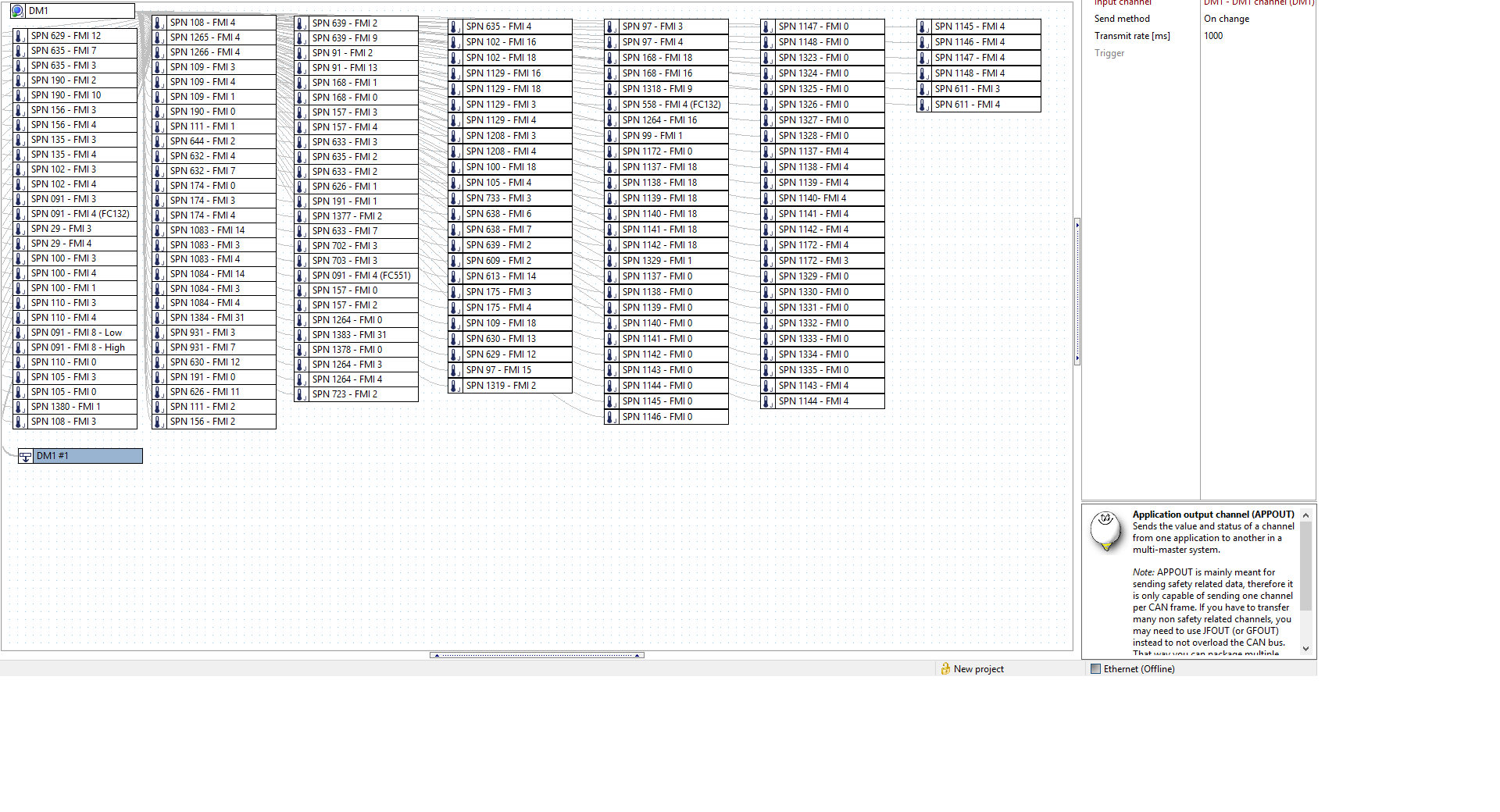
dm1 to multi master using appin/appout
Is there a way to either pass a DM1 message through appin/appout or have multi masters looking at the same DM1 messages from an engine. I have multiple masters and screens for an industrial app.
Customer support service by UserEcho


