 Simulation Battery voltage
Is there a way to change the +BAT diagnostic channel during simulation? I am doing some demonstrations that use this value to show engine charging voltage and it is stuck at 12.40V. I have a 24V system, so a low voltage error is persistent.

 Simulate and Canbus
Question for using simulate.
When testing a Project in Design we use the separate simulate program to test the design functionality. However when the deisgn uses Canbus as J1939 or CanOpen then it seems to me that I can go in and simulate a single canbus sent or received frame value to ensure that the system does what I want, but I cant simulate the live function of the canbus itself.
For example if I have a master that is sending J1939 packets to something else then is there any way I can generate that Canbus output on the Simulate PC as either a serial interface or using one of the approved USB to Canbus dongles?
So far when using one project master to talk to another master project then I dont believe I can really use simulate to test that but actually need the 2 master IQAN modules on my desk next to design to test the implications for change and to get a feel for canbus loading etc.
Is my understanding that I cant use simulate for this correct? and is there any plan's to change simulate to cover this aspect in the future?
In my case where I use a pair of MD4-10's to talk to each other over a wireless bridge having that much hardware tied up on my desk is expensive and I don't want to pay for that if there is an alternative approach I could/should use...
Andy

 Comments in Simulation Groups
Would it be possible to add a comments to simulation groups? I have a fairly complicated multi master program that I created a simulation file for. It would be useful if I could add comments to my simulation groups so that someone else could open my simulation file and more easily learn how to use it.

 Multi-Master Simulation
Hello,
Is there any plan to improve multi-master simulation?
Data is not sent between the masters, and therefore a machine can not be fully simulated.
This will make our future designs much more difficult to maintain.
Regards,

 IQAN Simulate 7 cannot see logic process in Design
IQAN Simulate 7 is operating different than previous versions. You can no longer see the logic processing in IQAN Design when you use the Run button. In simulate, you cannot see the function group logic to see which objects are true/false. This significantly reduces the debugging usefulness of IQAN Simulate. I am doing something wrong?

 External access to IQANsimulate variables
At the moment, it’s possible to manually simulate inputs and outputs in IQANsimulate.
However, I’d like to automate this process by connecting it with a digital twin of the machine built in Emulate3D.
The goal is to exchange data between Emulate3D and the IQAN simulation environment, so that the control software can be tested and validated automatically.
Is this kind of integration possible with IQANsimulate?
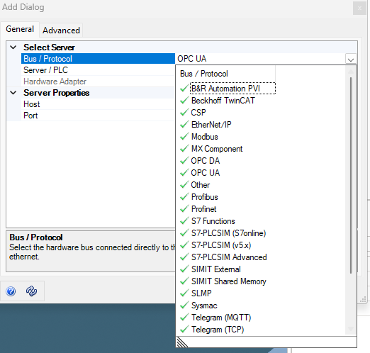
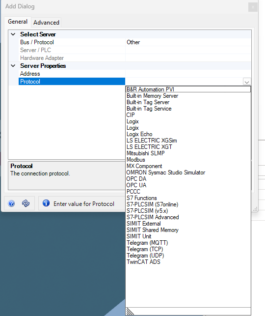
I have possible to use these protocols:


 Ability to mirror a connected display in simulate
It appears that it is not possible to mirror an actual connected iQAN display in iQAN simulate. I'm trying to capture images of what certain portions of our program would look like given different conditions on the machine. For the majority of items I'm able to use simulate on its own, but for heavily CAN driven display pages it's much harder, if not impossible, to simulate. It'd be very easy to create the different conditions on the machine itself, but taking pictures of the MD4 for user documentation just doesn't look as professional as screenshots.

 Delay off/on
Hello,
When simulating and/or troubleshooting in IQANrun delay on and delay off (for IDCs for example).
It would be great to know the current value of the delay.
Displaying a live timer of the internal value being counted down.
So if the IDC has a 240,000 msec delay on, you could tell how far along this delay was.
Regards,

 Simulate Input and Output Statuses
Is there a way to set the statuses for inputs and outputs in IQAN Simulate 5? I know I can set COUT channels, but that option is greyed out on all other channels.

 Simulate I/O diagnostics cases for HS or LS digital output on MC4X
It is possible to simulate different I/O diagnostics cases for i.e. current outputs on the MC43 by left-clicking on them and selecting status. A list of different I/O faults appear for the given output. However, when trying to do the same for a HS, LS or HS/LS digital output, the "Status" option is grayed out. I find this strange as the manual for the MC4X states that there are diagnostics for these output types as well.
Customer support service by UserEcho


