
 Maps in MD4
Hello,
Are there any thoughts about integrating some kind of map app to the MD4?
Like google maps or something for navigation?
For example:
-Add a GPS device in the machine and then add some kind of map function in iqan design for the MD4.
-Connect a smartphone to the IQAN system and use the phones gps to show location in some kind of app on the MD4. Or maybe stream the phones map interface on the MD4.
Just some thoughts and ideas. Not high priority.
Regards
Fredrik Forsberg

Iqan RUN adjust items must be organised in the adjust groups
For consistency reasons and short labels, you may have adjust items ( parameters ) with the same name in different adjust groups.
When in Iqan run reviewing actual settings it becomes impossible to know which one you are looking for,
My proposal is to have a possibility to organise the adjust items in the same way as in IQAN design adjust groups.

Byte Order for bit-sized CAN messages
Hello,
It would be great if IQAN allowed for Byte Order (Intel/Motorola) to be used on messages that are less then multiples of full bytes. Currently byte order can only be applied on 8/16/32 bit messages, but in some instances we may have a 12 or 14 bit message that requires endianess. We need to do some magic to reorder the bits before sending them, which is a pain.
For example, it is not possible in Parker to send the messages below with different byte orders, as they are not full-bytes.
Have Function Group Input names default to match the name of the respective input channel
I am doing a bunch with functional groups in the latest project to clean things up a bit, and it is annoying to have to individually name/rename each of the FGIs, especially when I change the name of the source and then "have to" rename it again in every Funtional Group where it shows up.
Maybe have a box to check to override the default name strategy for the times someone might want another name used.

Qcode function block with multiple outputs
Hi,
There is any plan to have a programming block to allow writing multiple external value. For example, update value to multiple parameters with the same Qcode. Actually, we have to write 1 block for 1 output.
It could be very interesting to be able to link external variable to be updated with this function block.
Thanks,
David

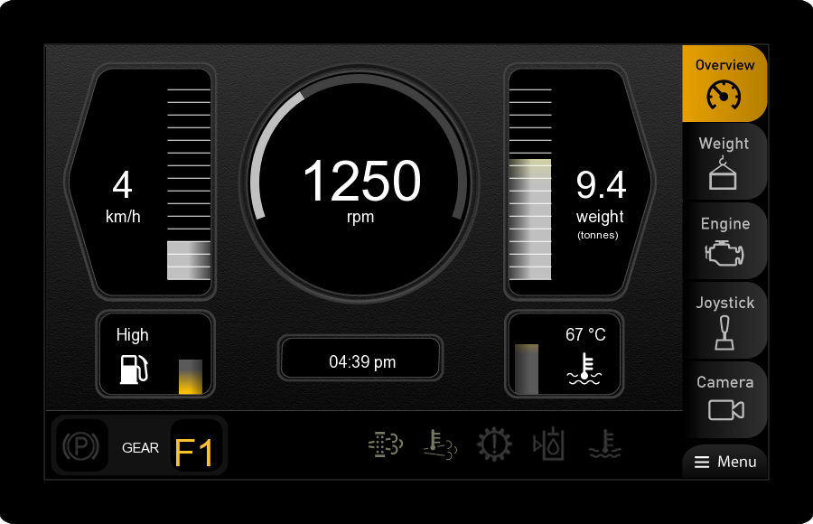
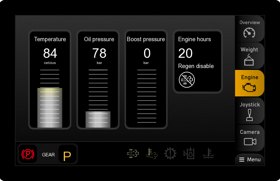
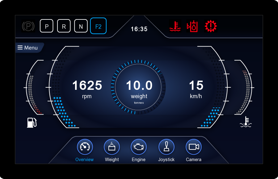
New IQAN-MD4 demo pages
Fork Lift, "Industrial" theme:
Fork Lift, "High Tech" theme:
Fork Lift, "Classic" theme:
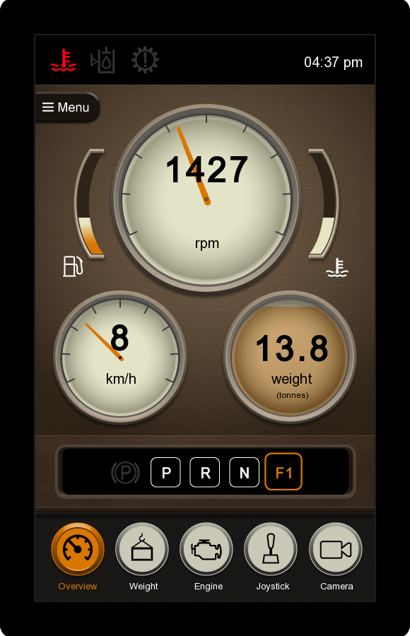
The pages were made by an industrial designer. He worked in Illustrator/Photoshop to make the graphical design elements, and then used them to build the HMI in IQANdesign. He offers his services to IQAN users, we can provide the contact details.
These are the files:
My Documents\IQAN Files\Examples\Fork lift\Fork lift.ida3
My Documents\IQAN Files\Examples\Fork lift\Classic.ids3
My Documents\IQAN Files\Examples\Fork lift\HighTech.ids3
Classic and HighTech use the same application as in Fork lift, but with different look and feel. They are stripped project files, but can be opened in IQANdesign in the same way as a normal ida3 file. Just select the correct file type in the open dialog, or double-click the file in Windows Explorer.

J1939 - SPN Library Included
J1939 -71 is now delivered as a large spreadsheet(digital annex) which makes it much easier to search. J1939 implementations from scratch is still a large task. Have you ever considered adding an SPN library to IQAN Design. Clicking on an SPN automatically assigns a parameter to the correct PGN frame with the default J1939 -71 descriptions. It also automatically adds that SPN to the DM1 list. I think this would speed up J1939 implementations.


Diagnostic Entries for application

Comments in Simulation Groups
Would it be possible to add a comments to simulation groups? I have a fairly complicated multi master program that I created a simulation file for. It would be useful if I could add comments to my simulation groups so that someone else could open my simulation file and more easily learn how to use it.
Customer support service by UserEcho


