
 Atan2 - two-argument arc tangent function
Any plans for the addition of Atan2 function?

multiple line button text
Did you expect to implement in the future the option to allow multiple text line in the button?
Actually, we can only have 1 line. In my understanding, I'm unable to do this.
Could be useful to minimize the space used when more text is required.
Thanks!

IQANdesign 4.04 released
Highlighted features
It is now possible to configure MD4 display pages for control with external buttons/encoders:
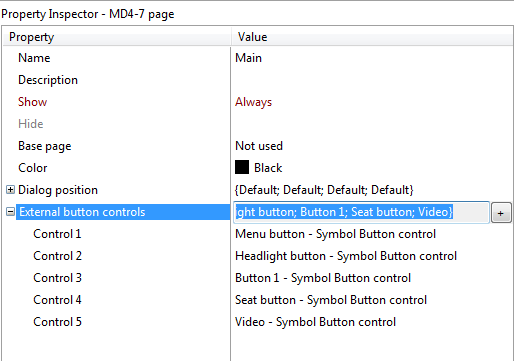
Activate/Navigate with Encoder or key Up/Down.
Interact with controls with key Enter, Slider and State selector will lock focus. Abort interaction (Slider and State selector) with key Escape/Menu.
Remove focus frame with key Escape.
Key interface is selected when using touch buttons, with external buttons/encoder, the spinner is used.
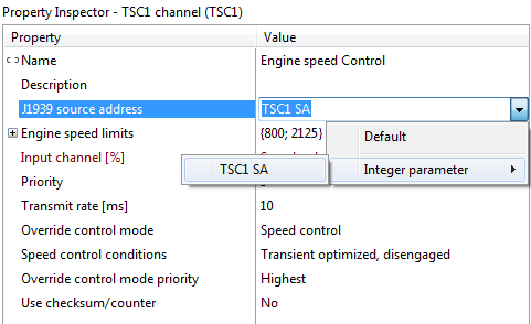
Property control of JFOUT and TSC1 source address
All master modules must be connected to diagnostic bus
Important problem solved
Triggered due to a touch chip communication problem, problem was introduced in 4.03. It is recommended to upgrade IQAN-MD4 applications to avoid this issue.
http://divapps.parker.com/divapps/iqan/Downloads/IQANdesign%204/ReleaseNotes4.04.25.htm
http://divapps.parker.com/divapps/iqan/Downloads/IQANrun%204/ReleaseNotes4.04.8.htm
http://divapps.parker.com/divapps/iqan/Downloads/IQANsimulate%204/ReleaseNotes4.04.14.htm

Channel Scope
I have been working with IQAN Design 4 for a few months now and would just like to say that having the ability to change the channel scope to public was a much needed addition. Some programs can get fairly large and any attempt at organizing the logic ended up in multiple FGIs and ended up being even harder to follow. That being said, I was quite used to the Function group output shortcut, shift+ctrl+o. It would be nice if there were shortcuts for the other scope options as well, or pressing the shift+ctrl+o shortcut to toggle through the scope options would also be handy. As long as I'm asking, It would be great to change the scope of multiple channels at a time.
Should logging of saturation warning be kept or removed?
When the COUT regulator on an IQAN-MC2 or IQAN-XA2 is unable to deliver the commanded current, the COUT gets the status saturated.
Saturation happens when it becomes impossible to deliver the commanded current, this is when the supply voltage is too low, the coil resistance is too high, or the max current has been tuned too high.
The available supply voltage depends on the +BAT supply to the module, the internal voltage drop in the COUT, and also on the maximum pulse width, that varies with the dither frequency.
An example of when a saturation warning may be triggered is during cranking in a 24 V system, where it is usually possible to keep the IQAN system powered up. There, if a COUT is tuned close to the maximum current that can be driven through the coil during normal operation, if an output is kept on during cranking it would have the saturation warning.
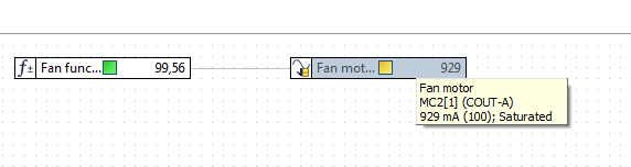
The saturation status can be seen when measuring on the channel, for example in IQANdesign:
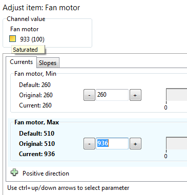
The COUT status can be seen when adjusting in IQANrun:
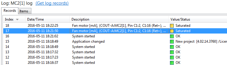
But the saturation warning also gets logged in the system log:
We have been getting some comments about the saturation warning, that it in some application just fills up the system log without providing much useful information for design or service.
Does anyone think that saturation warning in the log is useful?
Or that it should be removed?
11 |
||
0 |

Finite state machine comment
It would be nice to have the possibility to add comments to fsm channels so I can add a comment by transitions.

IQANsync available on App Store
We're excited to announce the release of IQANsync for iPhone. It is available for download on Apple's App Store now.
User Manual IQANsync HY33-8416-UM-UK.pdf
IQANsync for Android will be released later this year.
IQAN-G11 will be available in April.
Prior information about IQAN-G11 connection. IQAN-G11 connector info.PNG
A pre-release version of IQANconnect is available for selected users. Contact us if you want to be part of the pre-release test program.


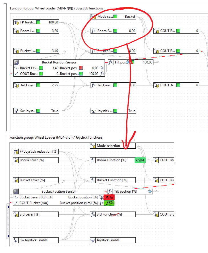
Status and value of channels hides name in online mode
when an application is not so clear structurized like below, it becomes sometimes hard to understand an application. In online mode it gets worse, as the status covers the name.
Quite often the area behind a channel box is free and could be used to show the values and status in one field.
Let me know your thoughts.
rgds Arno

NOT Visible Property
Sometime we have a digital which is just the opposite of the Visible property that we need and we have to create an other digital only for make visible or not a printed element.
If we could just write NOT in the visible property it will be great.

Add number of build
Hi
We can add the version of project in project protertie, it is okay, but the number of version don't encrease automaticly. It is possible to add the number of build and it encreased automaticly at each saving (or each hour, each days or each send). Like that I will now which build is in the product.
Thanks.
Customer support service by UserEcho


