
 XC10 DOUT(LS)
Hi everyone,
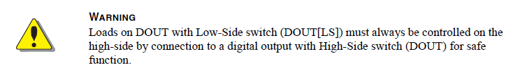
I have been working on a quite complex system. When using XC10 all relay coils (or valve solenoids) controlled by DOUT(LS) have been powered from +BAT and it has been working fine. However checking program, for no reason, have found in the the Instruction book that one or more DOUT should be used to power these coils or solenoids. Is there any risk with what I am doing ? I have checked that for MC43 and MD4, that I have been using on the same system, it is allowed to use +BAT for power. I can of course do it by book but the program would become a little bit awkward and messy.
Any comments will be much appreciated
Richard Kowalczyk
RKad Engineering
Australia
In the XC10 instruction book

XC10 POWER CONTROL input consumption
Can I know the XC10 POWER CONTROL input consumption or input resistance?
I cannot find this data in the iqan-xc10_uk_instructionbook 2016...
Thanks in advance and best regards.

XC10 Multiple Address
I have a project that uses one MD3 and one XC10. The XC10 sits on its on Expansion Bus CAN line with no other devices except for the MD3. Occasionally, during startup the XC10 will report multiple address.
Currently we tell the customer to power cycle the machine if this comes up and it typically goes away. I am looking into automating this if possible. I have tried a few things and have not had any luck. Is there a way to do a forced reset either on the MD3 and/or XC10 to try and reset the error?
Right now, the XC10's V+ supply is behind a relay so I can cycle it power directly. Testing this method has also not panned out.
MD3 cycle time is at 10ms. I read on a different forum post that the XC10 can only go down to 20ms. Ideally, I want to keep the cycle time as low as possible because of how the machine operates. Would going to 20ms help with the multiple address issue?
Are there any othe XC10 limitations I should know about?
Is there anything else I can experiment with to try and resolve the multiple address without the user’s input?

Multiple XC10s No Contact or Multiple Addresses Intermittent Issues
We are having issues with a system that has 2 XC10's on the same expansion bus. This is the first system we used multiple XC10's and have been having issues since we got it online.The XC10's expansion bus is connected to a MC43.
Changing different settings seems to have some affect but I feel like no matter how we change settings this issue is still around it just might not popup as much.
We either get a multiple address error or a no contact error. When we get the no contact error if we look online the device is working however any outputs that were active are faulted and we need to cycle them to get it going. This seems normal for a no contact issue. We see these errors on startup and occasionally while running.
Here are settings I changed. When I changed them I cycle power 25 times to try to gauge where we need things set. The settings I played with are the MC43 cycle time, expansion bus divider, delaying and staggering the 'Enable' for the XC10's. And I recorded the occurrences of each message.
There is a pattern but I'm having a hard time decided where to set things. We currently have the system set with settings that didn't give us problems during the test, but during further testing we occasional see them.
20 ms MC43
Expansion bus divider = 2(40mS)
Cycle util = 11%
XC10[0] Enable delay = 0000
XC10[1] Enable delay = 0000
0 - No Contacts
0 - XC10 Multiple addresses
10 ms MC43
Expansion bus divider = 2(20mS)
cycle util = 21%
XC10[0] Enable delay = 0000
XC10[1] Enable delay = 0000
0 - No Contacts
2 - XC10 -Multiple addresses
10 ms MC43
Expansion bus divider = 2(20mS)
cycle util = 21%
XC10[0] Enable delay = 5000
XC10[1] Enable delay = 0000
0 - No Contacts
2 - XC10 -Multiple addresses
10 ms MC43
Expansion bus divider = 9(90mS)
cycle util = 21%
XC10[0] Enable delay = 0000
XC10[1] Enable delay = 0000
0 - No Contacts
0 - XC10 -Multiple addresses
5 ms MC43
Expansion bus divider = 2(10mS)
cycle util = 41%
XC10[0] Enable delay = 0000
XC10[1] Enable delay = 0000
0 - No Contacts
4 - XC10 -Multiple addresses
5 ms MC43
Expansion bus divider = 2(10mS)
cycle util = 41%
XC10[0] Enable delay = 5000
XC10[1] Enable delay = 0000
0 - No Contacts
3 - XC10 -Multiple addresses
5 ms MC43
Expansion bus divider = 10(50mS) ,
cycle util = 41%
XC10[0] Enable delay = 0000
XC10[1] Enable delay = 0000
1(1) - No Contacts
0 - XC10 -Multiple addresses
5 ms MC43
Expansion bus divider = 10(50mS)
cycle util = 41%
XC10[0] Enable delay = 4000
XC10[1] Enable delay = 8000
1(1) - No Contacts
0 - XC10 -Multiple addresses

IQAN-XC10 max output current exceeded
What happens if I try to drive a load that is greater than 2.5amps with the HS output of a XC-10?

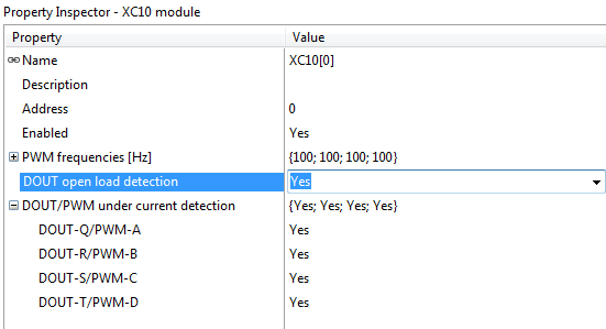
IQAN-XC10 with support for DOUT diagnostics
The updated version of the IQAN-XC10 with support for DOUT diagnostics has been released.
DOUT-A to DOUT-P
These high-side DOUT:s can be configured to detect open load when the outputs are off. The detection is based on a shared "strobe" function, giving out a limited current at regular intervals. The detection is suited for loads such as solenoids, but should be kept disabled if any of the high-side DOUT:s are driving smaller load, e.g. LED lamps that will blink when this feature is used.
DOUT-Q to DOUT-T
These low-side DOUT:s can be configured to detect open load when the outputs are on. This diagnostic feature is based on undercurrent detection. The detection is suited for solenoid valves, but should be kept disabled if the DOUT is driving smaller loads, e.g. most relay coils.
PWMOUT
The PWMOUT has open load detection based on measuring undercurrent also in previous versions. Now the option to disable undercurrent detection is available.
For more details on the DOUT/PWMOUT diagnostic features, see IQAN-XC10 instruction book, Appendix A.
IQANdesign support
The features are available with IQANdesign 3.15 and higher
IQAN-XC10 firmware version and serial number
The diagnostic features are available with IQAN-XC10 firmware version 2.02The IQAN-XC10 modules have a new serial number range:
S/N: 161726-000005 and higher
Customer support service by UserEcho


