
 XC43 Functional Safety
Will the XC43 (when paired with the MC43FS) inputs to be allowed for use in Functional Safety Marked Function Groups in a future version of IqanDesign?

 Driving Low Dither Frequency Valves with XC4x Current Outputs
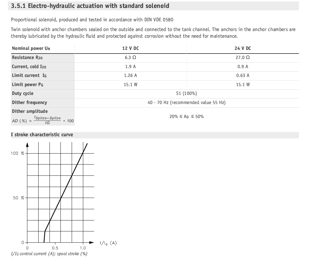
Has anyone had any success controlling valves that specify a low dither frequency below 71Hz with the XC4x current outputs?
We have a machine that is using a HAWE valve that specifies a dither frequency of 40-70Hz with 55Hz recommended. It also gives a range of dither amplitude of 20%-50%. The minimum frequency of the Cout channels on the XC4x modules is 71Hz. I'm sure 1Hz is not going to make a big difference if we set the frequency to 71Hz, but just wanted to see if anyone has had any similar experience or other recommendations. Just trying to avoid any possible stiction/hysteresis/chattering issues.

XC4x Firmware Updates
Say you have a brand new XC43. The firmware installed from factory is 1.0 (I think). How many times will the firmware update before reaching the current version of 1.03?
Also, the XC4x SIC module status lists a value of 140 as Firmware update. From the documentation that means the firmware update failed. Are there any other status values pertaining to the firmware?
What are the different values possible in the system info "InternalState" and is this channel accessible in the project?
XC44 HS+LS Overcurrent
We are experiencing a problem with the HS+LS outputs on an XC44 module connected to an MC43 as the master running IQAN 6.07. Pin C1:46 as the HS and pin C1:41 as the LS.
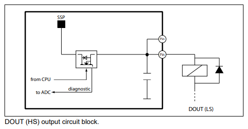
The outputs are being used to activate a solenoid. The circuit was wired to run through a relay latched by system estop, with a diode placed across the solenoid to protect the outputs as in the documentation.
This circuit is able to latch and unlatch the solenoid with no problems, and this was repeatable many times. However when the system estop is pressed for the first time and the relay unlatches and breaks the circuit there is no error. When the relay is energized and the circuit is connected again, when the output is turned on a message is displayed reporting that the LS pin is overloaded. This message then triggers on either side of the estop from that point on. Key cycle is able to "reset" to the first estop cycle. This behavior happened ~9/10 times the cycle was repeated. There were some occasions where the error did not trigger.
The overcurrent error will only trigger when the output is requested, the estop relay can be re-energized connecting the circuit and no overcurrent is reported.
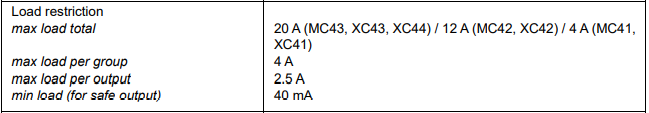
Current measurements were taken on the HS+LS wire to investigate. The current on this wire never approaches or exceeds the listed 2.5A. This is the only load on that pin grouping, the other 3 LS pins were not used.

Relay on XC43 HSDOUT caused Open Load error
We've used the 24V DC relay (datasheet is attached) on a XC43 High Side DOUT, but it doesn't seem to like the relay and show us a Open Load error. Could you please help us understand why this happened? Is there anything we need to pay attention to when using relay?Section-1_35_2018.pdf
Error during startup on XC44
Good afternoon,
I have a system that uses an MD4-5 as the master and several XCx modules as extension módules. One of the XC44 modules randomly fails to connect when I power up the system, and the LEDs indicate the following error:
"R4:3 3:1:7 Startup check. Expected after update of XC4x to FS capable version."
This error is random; it may not appear for a week or it may appear several times on the same day.
I have checked the wiring and it is correct, as is the battery voltage.

XC43 multiple DOUT overloads
We are having a problem with XC43 giving overload errors in multiple DOUT's at the same time.
Construction of the application is MD4 + 2xMC43 + 3xXC43, running with IQANdesign 6.08.
Problem is only in one of those XC43's. We use those DOUT's to control two different kind of solenoids, connected as shown below:
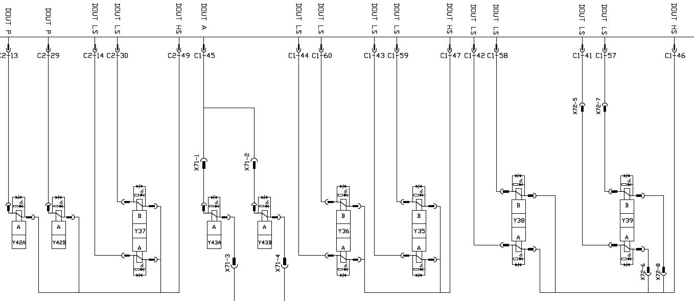
Fault codes are occurring only in:
- C2:29 (load 0,83 A), C2:13 (0,83 A), C2:30 (1,29 A) and C2:14 (1,29 A) overload simultaneously
- If you activate only one of these DOUT LS's, every one of those are giving fault code
- C1:58 (1,29 A) and C1:42 (1,29 A) overload simultaneously
- If you activate only one of these DOUT LS's, both of those are giving fault code
- C1:60 (1,29 A) and C1:44 (1,29 A) overload simultaneously
- If you activate only one of these DOUT LS's, both of those are giving fault code
Sometimes you can drive a day without having any fault codes, sometimes fault codes appear at the first activation at the morning. Even when the machine is standing still, only ignition on and you are activating those solenoids, it can be that you can activate those 50 times without problem and then suddenly the next activation gives you the fault codes.
We have replaced that XC43 with the other one installed in the same machine, still giving the fault codes. The original XC43 didn't give any fault codes when installed to another location. We have checked and measured all the wires, not shorted to the ground or to each others. Measured the coils, everyone has the correct resistance. Replaced all the diodes at the solenoids' connectors, no change. We have dozens of machines with exactly same construction and none of those are having the similar problem.
Any ideas how we should proceed with the troubleshooting? Thanks!

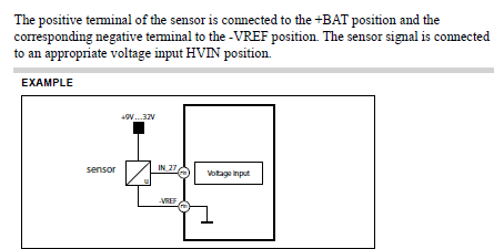
Max current on XC43 -VREF pins
We are providing some sensors with a 0V supply through the VREF circuit on XC43 module but cannot find the maximum current capacity of these pins. The manual states VREF has a limit of 150mA, but is this limitation on both the +ve side and -ve side?
I was under the impression -VREF is connected internally to the -BATT terminals, therefore does this mean there is a higher current limit? I cant find a value in the manual:

XC43 Output High
we have strange behavior which XC43 Has constant high output as soon as get powered on ,
we have replaced 3 modules but the same situation was income .
temporarily that output sealed and waiting for your advise .

XC44 address tag error / no contact
Hi Gustav,
We are experiencing issues with XC44 reporting no contact error and ID tag LED error.
Test bench system consists of the following:
- MD4-10 (6.08.24.8051):
- Adress tag 1
- Can bus A – terminated
- Can bus B – not used
- Can bus C – not used
- Can bus D – not used
- XC44 module:
- Address tag 2 (pin 4 and 20)
- Can bus A – terminated
- XC44 original harness on C1 and C2
- No inputs, no outputs for testing purposes.
- Tried different, known address tags
- C1 pins have been verified.
Pushing the project to the MD4 has not fix the problem. We tried the same setup with IQAN 7 – same results.
Our field service started reporting same issues in the field where the XC44 is reporting no address tag errors.
Customer support service by UserEcho


