 XC21 Digital out LS
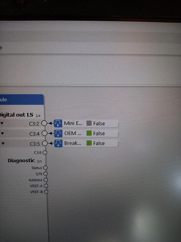
XC21. Is it possible to connect 2 Digital out LS in parallel to drive more load?
I want to connect a buzzer that draws about: 400mA

 Incandescent lamp on XC23
Hello,
I am using a DOUT LS on XC23 to drive a 12V incandescent bulb on an instrument panel. In steady state, the lamp draws 85 mA. I am getting an overload on this output when I try to activate the lamp. I was able to temporarely solve the problem by using a 22 ohms in series with the load. So I believe the problem is the inrush current of the lamp. The instruction book of the XC23 clearly states that the LS DOUT "are designed to drive small loads, e.g. lamps and buzzers". The example even shows a lamp being driven by a LS DOUT.
Can you explain if I'm doing something wrong. If not, is there any fix available to solve this issue ?
Thanks,
Guillaume

 XC21 Vref Error A
I have a system that uses an MD4 and some XC21 expansion modules. I am receiving an error code on the MD4 stating there is a VREF error A on XC21[0].
Currently our system uses the XC21 as digital inputs. We have a system power supply that supplies 24Vdc to a switch and then the digital input goes to the other side of the switch. This system has been running fine for multiple years, but now we have the Vref error.
Since I am not actually using the Vref + at all, I know it isn't overloading. That seems to be the most common answer, as the XC21 Vrefs can only output 70 mA. Is the error bring prompted because something internally is damaged and needs to be replaced?
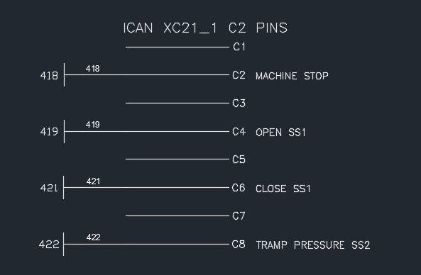
Her is a picture of our wiring. C5 and C7 are the Vref A + signal, which aren't wired. C2, C4, C6, and C8 are all digital inputs from our system, all being 24Vdc. The system 24VDC is also powering the MD4 and XC21 so there isn't a concern about different power sources.
Any thoughts?


 XC21 +BAT diagnostic value possible?
Is there a reason why the XC2x family of modules is missing +BAT diagnostic channel? I'm wondering if its a hardware limitation as the XA2 (below) and other modules appear to support it:
My customer needs to know the value of supply voltage on XC21 to read out on the master display. Unfortunately it needs to be a live readout rather than a digital flag if the module was to drop comms due to a low supply voltage. I will place a simple voltage divider circuit in if there is no workaround possible within the software but thought I would check first.

 DOUT error code flash on XC23 when output is disabled in IQANdesign
We have an application which has an optional function group containing a DOUT on an XC23 module. This function group is enabled or disabled using a digital parameter. With the function group disabled we get the output grey and 'disabled' state when measuring with IQAN Design, which is correct:

We also have no errors on screen stating open load (we have nothing connected to output because this machine has not got the optional extra fitted). XC23 module has error code flash of DOUT, I suspect open load. Its not logging any errors or open loads in any logs within master module, viewing state of the module using IQAN Run I also get 'OK' and no errors on status screen just the LED status is showing incorrect state directly on the module:
https://www.dropbox.com/s/gt9sga2eys10gg4/VID_20210720_101414.3gp?dl=0
If I delete the output from IQAN Design the error flash on the module disappears and it goes a steady amber flash, no errors.
Has this been fixed in a newer version? IQAN Design 5.06, MD4-5 M19 and XC23.

 XC-23 minimum input voltage
Hello,
I have an H-Bridge that drives a DC brushed motor on 12V. I need to determine the PWM ratio being supplied to this motor by the H-Bridge. There is no other signal that could get me this information so I am contemplating hooking both sides of this motor to PWM inputs on the XC-23. Before doing such a thing, I looked at the signal using an oscilloscope. Basically, the signal is 0-12V most of the time but dips below 0V when the ON time finishes. The lowest voltage read with the scope is -11V for a short period of time.
There are no Absolute Requirements for negative voltages on inputs in the datasheet of the XC-23. What is the absolute minimum voltage that can be applied to a PWM input of the XC-23 without damaging it ?
Guillaume

 Low side outputs protection diode
Hello,
I need to drive relays on low side outputs on the XC-23 and MD4-5. Do I need to use relays with included coil protection diodes or if the outputs of these modules are already internally protected ?
Thanks,
Guillaume

 Using two(2) or more low side outputs in parallel on XC-23
Hello,
I'm wandering if I could use two(2) or more low side outputs in parallel on the XC-23 to increase the carrying current capacity from 300mA to 600mA (2 outputs) or more. I have a relay that I need to drive that needs more than 300mA.
Thanks,
Guillaume

20mV jumps on VIN from XC23
We have an application for some voltage signals to be connected to the MC3 application. We have selected an XC23 module which compares a VIN signal on the MC3 with a VIN on the XC23. We have two of these functions (1 x MC3 VIN and 1 x XC23 VIN = one of two comparison functions in the application) measuring two different positions using sensors.
We have found that one set (an MC3 and XC23 VIN comparison) seem to follow almost exactly, however the other pair, the XC23 signal appears to increase and decrease in approx. 20mV steps. We are using VIN E and F on the XC23 and it appears the VIN F is causing the stepped signal even though it looks like it should have an accuracy of 1.22mV.
We have changed the sensor and XC23 module, but still appears to be doing it. Is there any reason for this behaviour? I have checked the VREF in the application, and all the VINs are configured to the correct reference voltage.
IQAN 4.05, application cycle of 50ms.

 Difference between XC21, XC22 and XC23
Thanks.
Customer support service by UserEcho


