
 When Can I expect an XC4 family of modules?
The MC41/42/43 looks like a great series of products, but I am reluctant to go with a 3 or 4 master system. When can we expect a series of expansion modules along the lines of the MC41/42/43? or am I stuck with the XA2 indefinately for current outputs?

 Slave Display (XD4)
We have been talking about how beneficial it would be if there was a slave display available such as an XD4. When added to the system layout, a slave display would have pages that would be assigned to it and functional virtual channels that could be used in any master application that could also be assigned to a it or any other system display.
We understand multiple displays may be used currently but as a multi-master system and this greatly reduces the ability for system flexibility and compatibility when all displays cannot be connected when sending a new program. The ability for single master IQAN systems to be backwards compatible with multiple module configurations without re-flashing every slave module in the system is what sets it apart from others like Plus+1.

 XC43 Functional Safety
Will the XC43 (when paired with the MC43FS) inputs to be allowed for use in Functional Safety Marked Function Groups in a future version of IqanDesign?

 Directional Motor Control with COUTs
Hi all,
I'm thinking about controlling a motorized hydraulic pressure relief valve (the motor turns the pressure setting in and out) with two COUTs on an XA2 module. The motor was previously controlled with a couple of digital outputs and relays as an H-bridge. This is more of a XA2 hardware question; are the diodes necessary to protect the high side COUT as shown?:
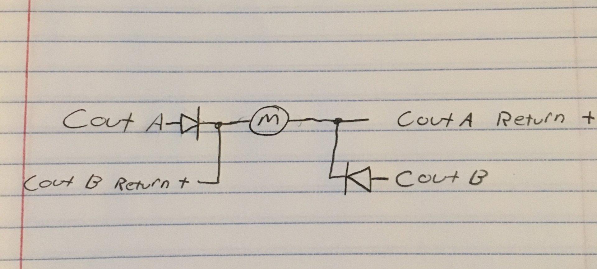
Obviously only running either COUT A or COUT B at a time.
Or are diodes not needed?:
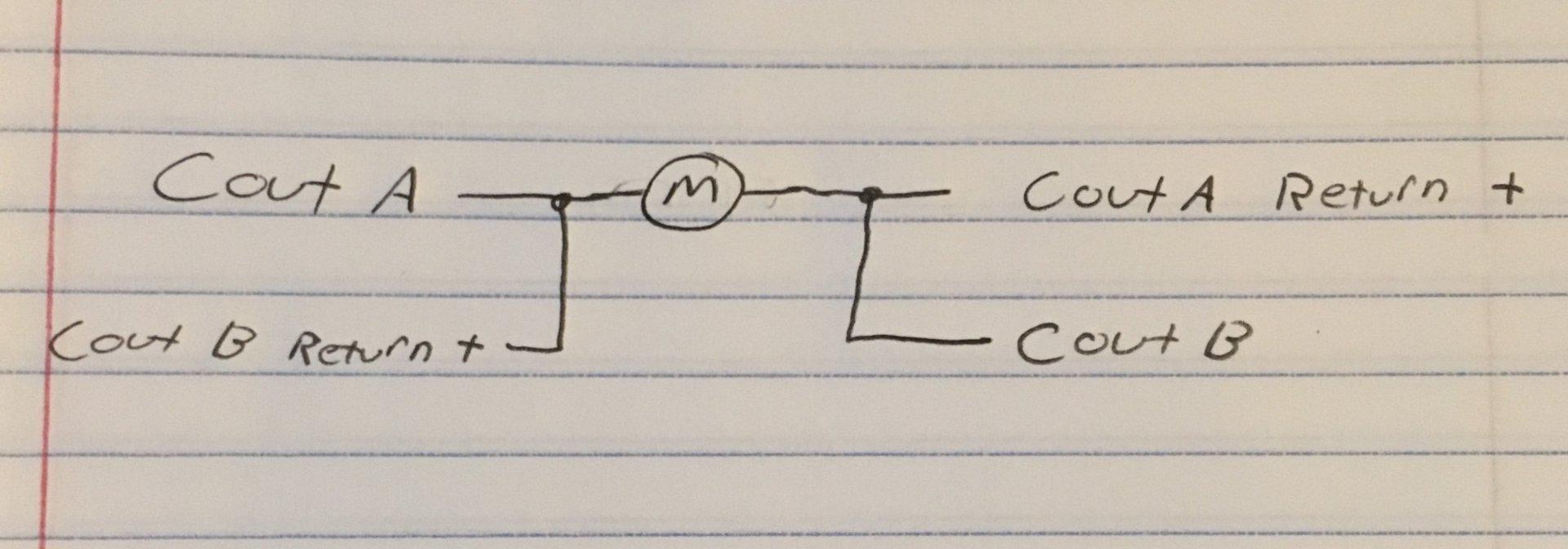
Thanks,
Luke.

 troubleshoot output low xt2-a0 c1:19 675ma

 Driving Low Dither Frequency Valves with XC4x Current Outputs
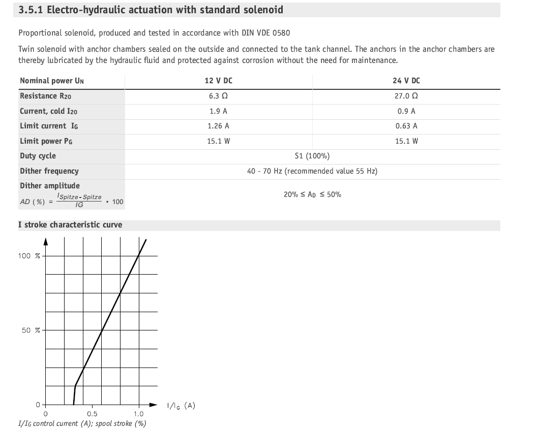
Has anyone had any success controlling valves that specify a low dither frequency below 71Hz with the XC4x current outputs?
We have a machine that is using a HAWE valve that specifies a dither frequency of 40-70Hz with 55Hz recommended. It also gives a range of dither amplitude of 20%-50%. The minimum frequency of the Cout channels on the XC4x modules is 71Hz. I'm sure 1Hz is not going to make a big difference if we set the frequency to 71Hz, but just wanted to see if anyone has had any similar experience or other recommendations. Just trying to avoid any possible stiction/hysteresis/chattering issues.

 XC4x Firmware Updates
Say you have a brand new XC43. The firmware installed from factory is 1.0 (I think). How many times will the firmware update before reaching the current version of 1.03?
Also, the XC4x SIC module status lists a value of 140 as Firmware update. From the documentation that means the firmware update failed. Are there any other status values pertaining to the firmware?
What are the different values possible in the system info "InternalState" and is this channel accessible in the project?

XC44 HS+LS Overcurrent
We are experiencing a problem with the HS+LS outputs on an XC44 module connected to an MC43 as the master running IQAN 6.07. Pin C1:46 as the HS and pin C1:41 as the LS.
The outputs are being used to activate a solenoid. The circuit was wired to run through a relay latched by system estop, with a diode placed across the solenoid to protect the outputs as in the documentation.
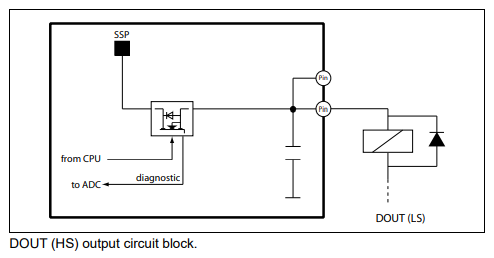
This circuit is able to latch and unlatch the solenoid with no problems, and this was repeatable many times. However when the system estop is pressed for the first time and the relay unlatches and breaks the circuit there is no error. When the relay is energized and the circuit is connected again, when the output is turned on a message is displayed reporting that the LS pin is overloaded. This message then triggers on either side of the estop from that point on. Key cycle is able to "reset" to the first estop cycle. This behavior happened ~9/10 times the cycle was repeated. There were some occasions where the error did not trigger.
The overcurrent error will only trigger when the output is requested, the estop relay can be re-energized connecting the circuit and no overcurrent is reported.
Current measurements were taken on the HS+LS wire to investigate. The current on this wire never approaches or exceeds the listed 2.5A. This is the only load on that pin grouping, the other 3 LS pins were not used.


 XC42 DOUT HS working with high impedance inputs
Hello,
We are designing our last machines with XC42 instead the phase-out XC10 and we are experiencing some issues.
One of them is related with the activation of some Inverter (Euradrives) and Soft Starters (ABB) digital inputs.
When the DOUT HS is directly connected to those high impedance inputs and the output is OFF, surely due to the leakage current, the Inverter and the Soft Starter interpret it as ON state, so they run untimely!
It is possible to reproduce this just wiring a DOUT HS to a DIN PD, the input will be ON all the time, even when the DOUT is OFF:
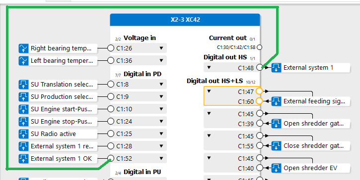
Also, when the inpedance is very high (not with XC42 DIN PD in this case), the DOUT HS is ON, the Open load error appears due to low consumption of the high impedance inputs, and this checking cannot be disabled in the IQAN...
We thought to add and extra resistor in parallel to the high impedance input to avoid this error, but we don't like this "solution", it can be really dangerous because if the resistor is broken or loosen, the devices will be running untimely!!
Our only solution was to add 24Vdc relays in the HS outputs and wire the contact of the relay to the high impedance inputs.
We think that the best solution would be the possibility of disabbling this leakage current for Open load ckeching in the DOUT HS. Is there any possibility of implanting it in future releases?
Thanks for your help and best regards,
Adolfo
Customer support service by UserEcho
