MD4 Graphics Options
Another nice option would be to be able to fill in areas bounded by lines with blocks of colour which could be selectable by another channel. I know that this is possible by creating colour images and then imputing them but this would be a much easier method.
Another thing which we seem to get requests for regularly is the ability to graph items on screen. I have asked whether this might be possible before but up til now this functionality has always been too video processor hungry - I wonder if the new spec of the MD4 might now be able to cope with it?

Visual compare tool
Because for big project the text files compare is difficult to use.

Mode selector for "Text Formatting Channel"
It would be nice to be able to assign a State machine or parameter to a "Text Formatting Channel".
I have a situation where I have "Group A", 10 Text Parameters with with a state machine (10 states) assigned to it. And a "Group B" of 15 Text Parameters with a 15 state machine. I would like to use a Single Text formatting channel to Add Group A to B for certain situation.
Trying to display the text on the screen currently is painful.
Also on a separate note it would also be nice to be able to use a Text Formatting Channel in a Text Parameter.

 application input output vs j1939 input output for master modules
If I understood it correctly, an MC2 master received a digital value from an MD4 master module via an application in/out pair.
Then in another location in the program, the MD3 and MD4 exchanged information through J1939 pgns.
How do I know when to use Application in/out or J1939 in/out?

Md4 and frequency
Hello
It is possible to measure a frequency with a md4 ?
Thank

360° Rotation of Gauges
I have an application where I am using a gauge to display the position of a rotating object. I make the 12 o'clock position the 0° point. I noticed that as my input is rotating from clockwise, that the needle on the gauge rotates counter clockwise from 359° back to 0°.
It would be nice to have the gauge continue to rotate in a clockwise direction as my input crosses the 0° threshold.
 Portrait scale from MD4-7 to MD5-8
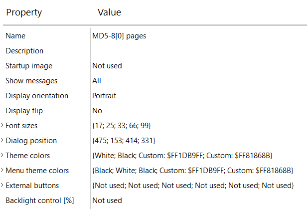
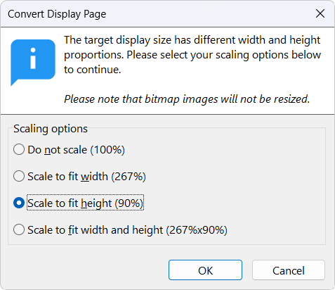
Hi all, converting portrait pages does not seem to work properly. Utility treats it like my destination screen is horizontally mounted which is not (see first picture). Scaling only applies to horizontal proportions (see second picture). Height should be 1280/800*100 = 160% and width 720/480*100 = 150% ? What am I missing here ?

MD4 refresh rate for specific variable using 6.08 IQANdesign
We would like to update a specific variable on the MD4 at a frequency of 4 Hz, rather than at every change based on the MD4's 50-ms cycle time.
How can we do this in a simple and optimized way?
md4-5 firmware 6 to firmware 4 update
I have a MD4-5 master display that is blank with firmware version 6 but the IQAN program for it is IQAN 4.06. I need to back update the firmware to version 4 to be able to program it with the program.
QCode Documentation
Does Parker provide documentation for the code syntax used in QCode?. I normally just guess and let the assistant complete things for me. It would be nice to have documentation the lays out and explains all of the options. Thank you
Customer support service by UserEcho