
 PSVG GPS coordinates
Greetings,
Anyone know if it is possible to get the GPS data, specifically coordinates, from the PSVG into the IQAN program?
UTS v2.5
Hello,
I am having issues communicated with a UTS V2.5 +- 90 XYZ sensor over J1939.
I've tried the UTS version 2 app shared on this link:
https://forum.iqan.se/communities/1/topics/1057-universal-tilt-sensor-uts-programming-shortcut
Seems from that thread the app may not actually work, and documentation may not be up to date.
Anyone have any luck getting this to work?
If so, are you willing to share either a sample app or provide some insight on what needs to change in the UTS version 2 app to make it work?
Using version IQANdesign v6.08.

Why is the largest value of a 32 bit integer limited in IQAN?
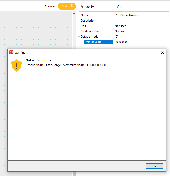
I am trying to store a 10 digit serial number inside my MC43FS code on IQANDesign 7.02.
Unfortunately I have found that the serial numbers always start with 2 and IQAN is limited to storing 2000000000 as an integer parameter.
The system will not accept storing 2000000001.
Why is it that a 32 bit signed integer is limited to 2000000000? The max value of a 32 bit signed integer should be 2147483647.
Edit: I should note that a text parameter cannot be used in this scenario because I must compare the serial number to see if it has been updated/changed throughout the life of the product and take action when it is changed. I am trying to avoid stripping off the 2 and including instructions for technicians to update only the last 9 digits because I can't automatically populate a 2 at the beginning in IQANRun or IQANGo. I am afraid that will net us the first 9 digits of serial numbers if techs don't read the instructions closely.

Numerical order sorting arrays
Hello all, I have numbers in an array that need to be sorted numerically (from small to large). Does anyone have any functions that may be useful? It would also be useful to get the reordered number's index values.

"Multiple fast JFOUTs" functionality
I have a program where I need to send two JFOUTs at 10ms transmit rate. With the application cycle time set to 50 ms, I get a warning about "Multiple Fast JFOUTs" in the program. The manual and the help window state that "One JFOUT channel with send method Continuously is allowed to have a transmit rate faster than the cycle time. The resolution for that single channel is 10 ms."
What is the expected behavior if there are multiple fast JFOUTs? I flashed the program to a module and observed the two JFOUTs are transmitting at 10ms each. If I set the application cycle time to 10ms this warning goes away, but what are the potential issues with running two JFOUTs at 10ms transmit time with the module cycle time set at 50ms? Unless I'm overlooking it, the manual doesn't really outline what the behavior is with this warning present.

Troubles receiving a CAN Message on JFIN
Hello, I'm trying to use a CAN current sensors for some monitoring and I need it to be on my J1939 bus as i dont want to run a dedicated CAN network to these sensors. The messages are sent from the device as the fallowing :
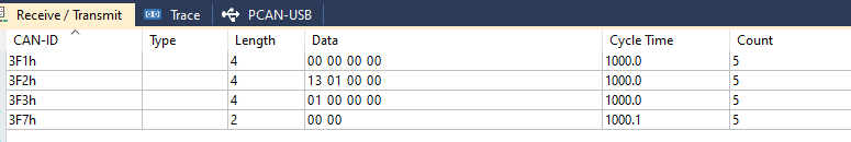
How do I set up My JFIN channel to accept this message ? I have my bus source address set to 3 and my destination address set to 0xF1 but I do not receive a message. I have tried several other settings but I am not able to receive the message

Open load error with feature disabled
I'm using Iqan Design 7.02.20.9286. I have DOUT-HS open load detection turned of on a MC43. I am still getting an error on the screen for open load. The circuit only has a Deutsch W2S-SDT-12V wedge lock for a load. Is there a problem with the software? What am I doing wrong? In this configuration on our machine this plug does not get used. Is there anything else i can do with the software to stop the error?


Is it possible to select a language in IQAN design for GUI development
I am adding a language to our system and was wondering if theres a way to switch the language so that the display pages will show it. A lot of the translations I have are much longer than the english words and are all overflowing and it would be much easier to edit them to fit if you could change the language in IQAN design. I tried to see if I could switch the default language to the new one, but it doesn't let you.
Language Selector
Is there a way to change the language outside of the preferences menu? For example, I have digital parameter to change multiple things and want to also have that parameter choose the language.
Customer support service by UserEcho


