
 Unable to change values (size of property inspector)
I am unable to change values in 6.04 Design. I have the ability in 5.07. Uninstalled and reinstalled to no avail.

We have tried accessing a machine remotely and have the following message "no reply from IQANconnect server". is this a problem on Parker end?
We have tried accessing a machine remotely and have the following message "no reply from IQANconnect server". is this a problem on Parker end? We have tried 2 PC's and have the same message.

Bluetooth enable G11 gateway
I did set the G11 enable on false and also the Bluetooth enable on false, but still I can connect with IQANGO, and for example change the system ID. How can I disable the Bluetooth radio?

 CAN bus D failure
I'm having an issue with a My CAN bus D on an MC43. It had worked the other day then I had made a program change and now it continually gives me CAN Bus failure faults. I have disconnected the wires so there is no chance of a wiring issue. I have made a simple program that only sends one PGN out and that also fails. I have used known working code that i swapped from Can Bus E and the problem continues on D. This is happening on two different panels that I have. I have to think that it is some type of bug or the MC43 needs to be rebooted in some way but I have already sent a blank program to it.

Get parameter on SP changes type from Integer to State after first run
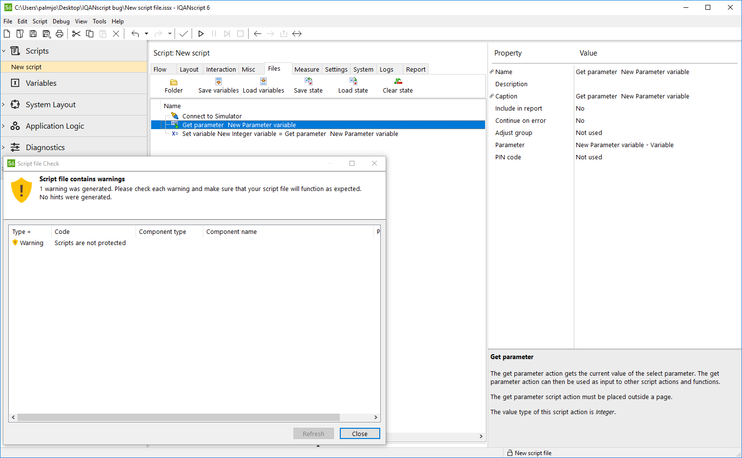
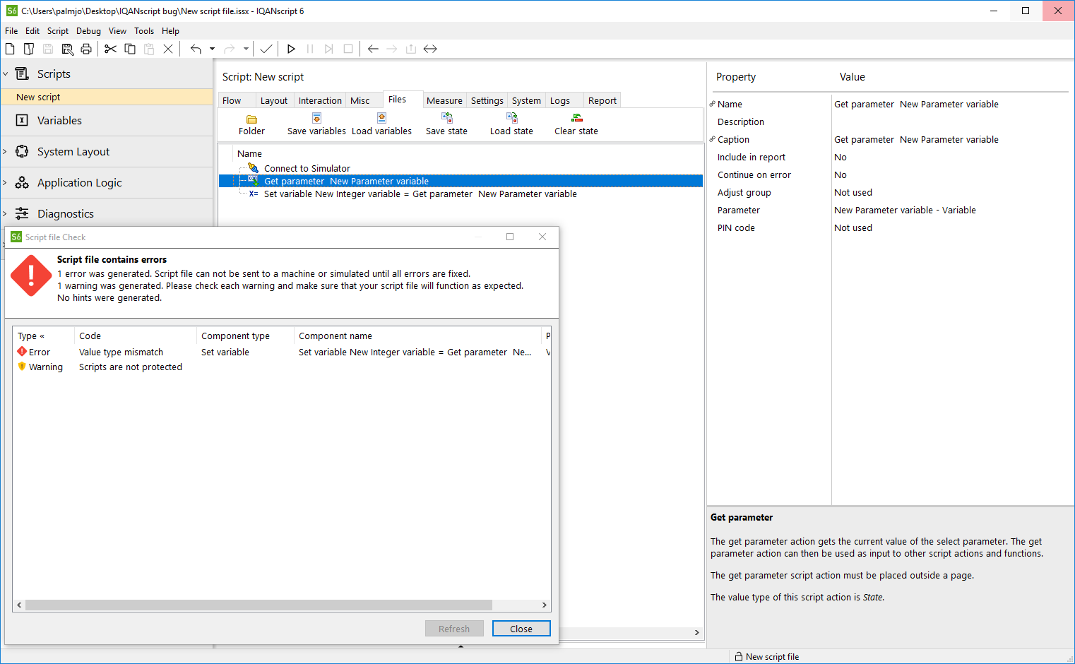
The value type of Get parameter is initially Integer, but after successful execution, the value type changes to State (see bottom right corner) and Script file Check throws a Value type mismatch error for Set variable since it's not allowed to assign State values to Integer script variables.
This was tested with IQANrun 6.04.2.5572, IQANscript 6.04.1.5081, IQANdesign 6.04.5.5888, and IQANsimulate 6.04.1.5081.
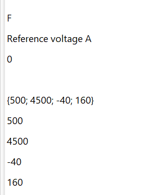
Initially:
After execution:
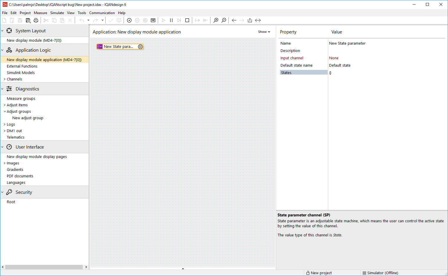
The IQANdesign project used contains only an adjustable empty State parameter channel (SP).
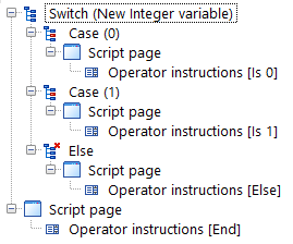
Script hangs on switch-else despite switch-case evaluated to true
The attached script was created in IQANscript 5.07.1.4875 and tested in IQANrun 5.07.1.5363 as well as IQANrun 6.04.2.5572.
Creating the script in IQANscript 6.04.1.5081 makes no difference.
The script hangs on a blank page in IQANrun after either switch-case has evaluated to true and it's not possible to continue execution.

IQANgo on Android phone (China)
Hello
We are preparing ourselves to commision a prototype in China with a G11. IQANgo cannot be downloaded on a local Android phone. Is there a hidden way to do so??? Can anybody help??
Regards
Andy Pauly

Dynamic Source Address Claimed by Sensor
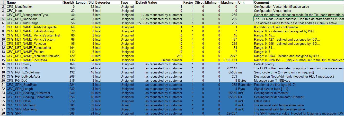
We are using a pair of STW T01 J1939 Temperature sensors connected independently to the "C" bus on an MD4-7. The sensors create dynamic Source Address on start up - am looking for a way to use the Initialization Function group to read the two source address' and populate that value into the appropriate sensor source address field. Assume we can use CFG_NET_AddrRange to read that value but not sure a) how to identify one sensor from the other and b) once the value is read to populate the source address into the source address field?
Dynamic address claim
We are a manufacturing company utilizing MD4's and MC43's to control Hybrid transmissions. I want to be able to keep the same program and not have to adjust the source address all the time. These transmissions must connect to each other over CAN and communicate for several functions. The address claim in Iqan will disable if two modules have the same address. Is there a way to make them dynamic so if Address EX: 23 is already taken it will move its address to 24 and so on. I have used the Initializing source address to make these adjustable but its not really ideal as these could have to be setup daily.
Customer support service by UserEcho


