
 No uniCAN handle
I'm getting this error when downloading to MD5:
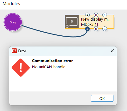

Trying to download software using NI 8473 but seems to error before even establishing connection with the display. I noticed the MD5 does not have built in resistor and I have not installed one as yet, could this affect the download from PC?

View settings
How can I view settings for my machines without logging into them. I have the setting files *.irsx

I would like to read certain parameters I will us in my control from a file
I want to be able to use 'constants' in my IQAN read from a file, for example perhaps using the same control system across multiple vehicles but having some vehicles with a lost maximum speed. One way I would use in other systems is a vehicle configuration file to rad the values from.
I saw the 'variant option selector' which sounded like it might be part way there but it complains it wants n option group and I have no idea how that works never mind if it is the right thing to use

Communication Error IQANgo
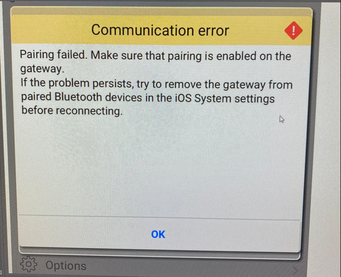
I have been receiving reports of our service guys having trouble with connecting to our machines via IQANgo. We have seen this message on 3 different phones and 2 different machines. One had a fresh download of the program, another deleted the app and reinstalled it after receiving the error, and the third had the second one try after they received the message.
The first was a customer and the problem cleared after he returned a subsequent day. The second and third are our service guys and have had no issues connecting to other machines. Any ideas on how to fix or avoid this?
IQANgo latest version
IQANdesign 6.08.30.8216

View settings IQANrun 7
How can I view the settings in IQANrun 7 from a settings file or clone file? I would like to print these, but I can't get them onto the screen at all. Thanks in advance for the explanation.

Multiple messages with identical PGN
How do I capture messages in IQANdesign 6 (I can update if required for feature) with the same PGN? I have multiple pumps on one CAN network that feature J1939 style addressing, and each of these pumps has an identical status message in the .dbc file with the exception of their source address - the messages are PDU1 J1939 PGN. I have unsuccessfully tried importing these messages using CAN Generic Frame, but it seems IQANDesign overrides this and reads it as a J1939 Frame In and looks at PGN instead of extended CANID. How can I collect the information for each of these pumps separately in IQANDesign?
For reference, CAN IDs in HEX:
Pump 1 address = 0x18FF2301x
Pump 2 address = 0x18FF2302x
where PGN is FF23 on both pumps.
 Cannot Export Files from IQANgo on Android
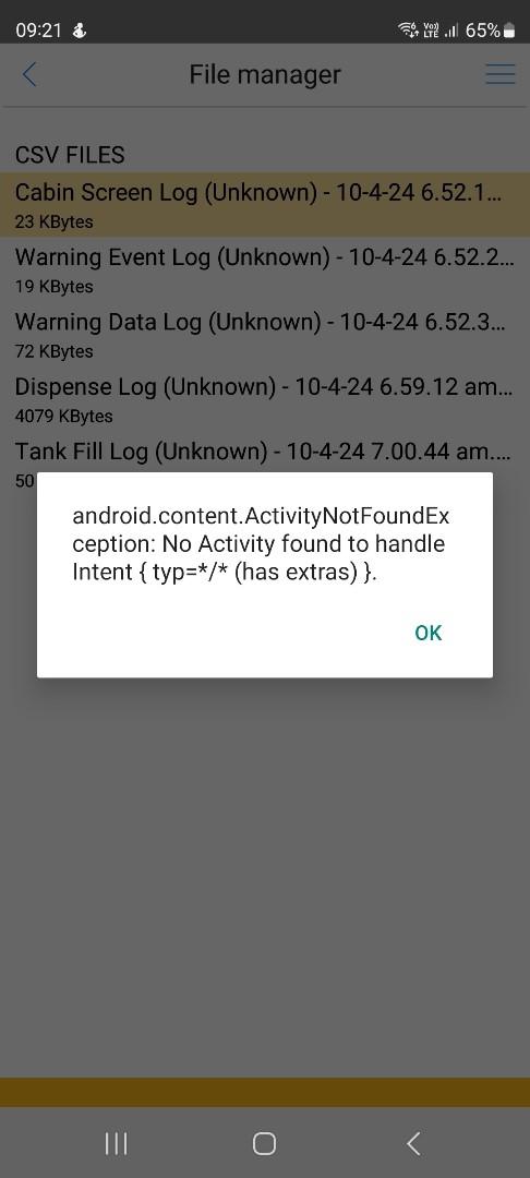
A customer notified me of an issue with IQANgo on Android - when attempting to export a log file from the app an error window appears as shown in the attached image. I managed to reproduce the issue myself on another Android phone. Both phones have the latest Android version, as far as I know this has just started with the the latest IQANgo app version 7.02. May you please investigate?

Disable DM1 on Bootup
Hello,
Is there way to disable DM1 Out on bootup for a period of time while everything starts? Same way logs can be disabled.
Thank you,
Gord
I have a requirement to send TSC1 to two different destination addresses
I did NOT design the messages required for this system so please dont blame me or tell me I need to change them, this is not in my control.
But the requirement is for TSC1 to go to destination 10 AND destination 90. I cant have 2 messages with the same PGN it complains, I cant see how to specify two destination addresses for one message. I am aware of 'broadcast' but do not believe at the moment the two components will pick up the broadcast rather than looking specifically for their own address.
Does anyone have a clue how I can solve this issue?

Shutting Off Engine With Timer
I have an application that has a seat switch timer. When the seat switch sees a negative flank and stays false for 8s, I would like the shutdown the engine. I have the shutdown JFIN configured but I am not sure how to go about sending a message to the engine to command it to shutdown.
Customer support service by UserEcho


