 Move Function Group Around Under 'Application Logic'
I have added function groups in the tree on the left hand side in the wrong order and it seems you cannot move them around. Operationally it has no effect, but to please the eye ideally I want to have Start/Heartbeat to the top and have slew and boom underneath. I cant seem to find a way of doing it aside from deleting or renaming them and transferring the contents? May be missing something but if not, can we have a feature added to move them around by drag and drop please?


 Cant extract clone from iqan run 2, with windows 10
Hi, i cant extract clone from mdl-1 or mdl-2 unit with iqan run 2 under windows 10. I know that other persons on my company has the exact same issue. But if i use same iqan run 2 software with windows 7 it worx. Any ideas on how to solve this? by the way i can extract settings but not clone. In the middle of the extraction process (in win 10) i get connection lost.
/Daniel

 DM1 Out with Occurance
I want to use the DM1 Out function which is very helpfull for my project. So thanks! But can I also send the Occurance with the DM1 message?

 Can you also use UNsigned integers in iQanDesign?
I want to use a 32 bit UNSIGNED integer. I don't see how I can change the signed integer to unsigned. Is this possible?

 Adjust Item Enable Not Working
I'm seeing an issue in IQAN7 and IQAN6 where if I create an adjustable state parameter, place the SP as a button on a display page, assign an enable property at the adjust item level, it will not enable the button no matter what state the enable property is in. I attached an example project file.

 V7.00 Crashes when opening MD4-10 display screens originally made in V6.08
V7.00 Crashes when opening MD4-10 display screen originally made in V6.08 but converted to V7.00
I have 40 screens.
I ran a quick test with one display screen made in V6.08 converted to V7.00 and this worked perfectly.

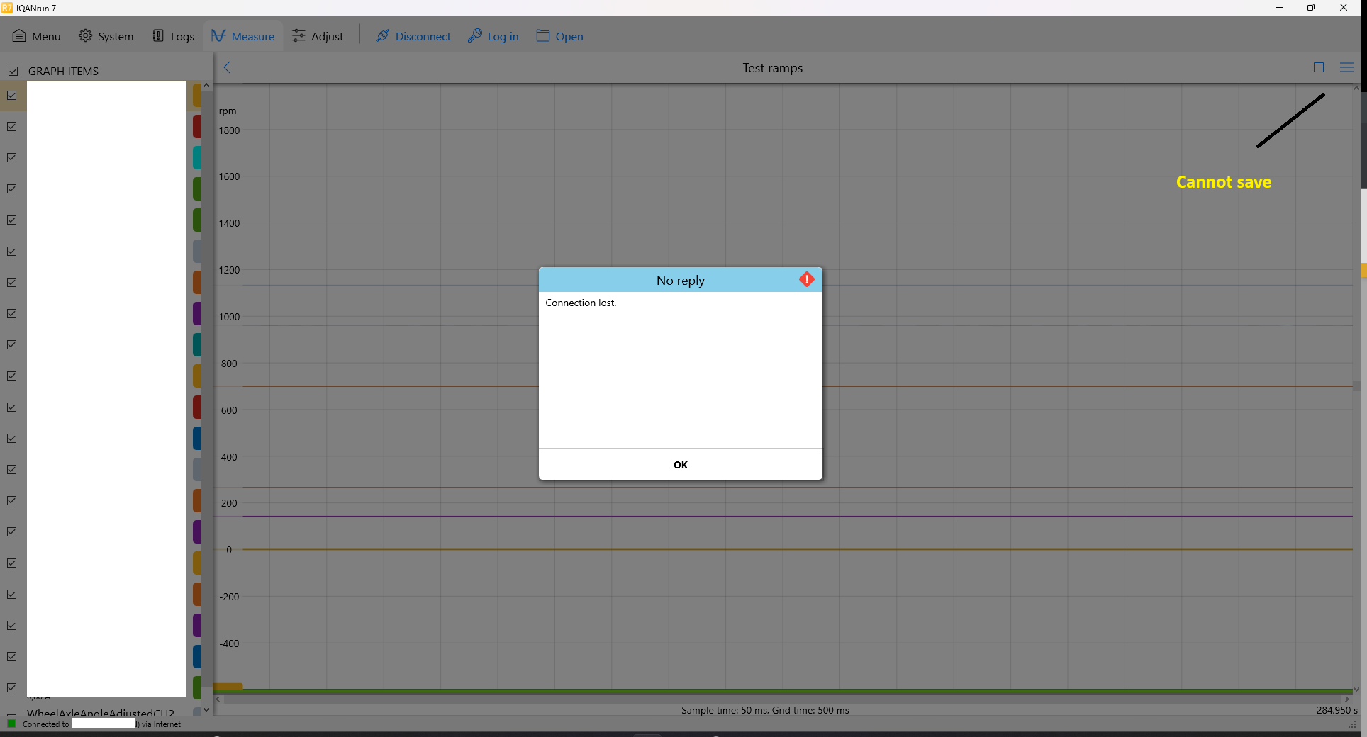
 Measurement deleted when IQANgo disconnects from IQANrun 7
I have a customer connected with IQANgo to a machine with G11. I connect remotely from IQANrun through the servers and start measurement in a measure group.
This measurement could go on for several minutes in order to capture an intermittent problem.
If the machine shuts off or the phone gets disconnected from the Internet I get the following message:
"Connection Lost"

I try to click the menu button for saving but nothing happens.
As soon as I click OK in the dialog box all measurement data is deleted and IQANrun goes back to the start screen.


 Adjustable PGN Value
I am in the process of setting up an external function group for a third party controller. It uses J1939 communication and at least one of the PGN values changes based on the source address of the module. I could not find a way to make the PGN value adjustable in any way. (No dropdown to select a channel value.) I plan to use a few of these third party controllers in systems and therefore will have different source addresses. Is there a way to change the PGN value other than directly typing it in the JFOUT/JFIN channel? Ideally I would like to either use an integer parameter, maybe in an initialization group or integer math in this case since there is a base PGN+SA to make up the different PGN values.

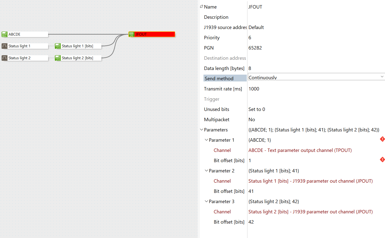
 Fixed size text parameter in JFOUT
I have a J1939 device that requires a 5 byte fixed length text parameter in the beginning of a frame.
After that parameter there are several 1 bit parameters for controlling lights and relays.
I have tried to set a static length of the TPOUT and Delimiter="Not used" but I still get the error "Text parameters not last in frame"


How can this be solved?

 G12 Android Connection Issues
We have recently started using G12 modules in place of G11 modules, and are getting Bluetooth connection issues with some Android devices. On the same G12, iOS devices and Windows laptops will connect over Bluetooth with no issue, but when attempting with Android it never connects. Swapping out the G12 for a G11 solves the issue on the same system. Are there any known issues with Androids and G12 currently on the Parker side?

We ended up figuring it out, Apple/iOS devices allow you to use a 4 digit connection PIN code without having leading zeros. Example being "1234" will work as a connection for all iOS devices, but typing that in on an Android device will cause it to fail connection. Typing in "001234" will allow a connection on Android in this instance, but will cause iOS devices to fail connection.
Customer support service by UserEcho


