
 MC42FS Error code R4:2 1:1:3 I/O startup test failed
Got the R4:2 1:1:3 I/O startup test failed error on a MC42FS module.
Even when I only put power (24v external power supply) and a address tag on it.
Tried to put an empty program on the controller. The controller is installing the program but when it restarts it keeps coming back with the same error.
Is there anything I can try to fix this?

HS+LS output EMF capability
Would like to use the HS+LS configuration to control the HV contactors in an Hybrid configuration. I am reading note about using Diode to protect against EMF. But I cannot find specification on acceptable EMF level? Our contactors have built-in EMF clamping diode rated at 150V?
Also how does the open circuit detection in an off state works? injecting a current i am assuming. How much? Just want to avoid issue with Dropoff voltage for the coil.

Driving Pulsar with the PWM on MC43
Hi There,
Hope all is well,
Is there any possibility to drive Proportional 24v 33Hz Pulsar valves with the PWM outputs from a MC43 ? Reading the manual it states that this will not work from MC43,but reaching out to see if it is possible.
ATM I am using the proportional flow from the pump and making the Pulsar more like an ON/OFF, This is working currently but would like to use the Pulsar proportionally.
Thank you

MC4x/XC4x 12V 30W solenoid overload error
What is the suggested solution for driving NG6 valves with standard 30W solenoids at 12V system voltage with MC4x/XC4x modules?
We use the HS+LS digital outputs for driving Parker D1VW valves with "K" code solenoids in a 12V system. As stated in the instrucion book, max load per output is 2.5A, but the measured current is 2.7A (as in the D1VW catalogue). The measured solenoid resistance is 5 Ohm, but it should be within 7-14 Ohm (MC4x/XC4x instrucion book).
30W solenoids are standard at other valve suppliers too, so changing the valve isn't an option. Change the system voltage to 24V also isn't possible for this project.
MC41 - M18-4 Barrel Speed sensor
Hi,
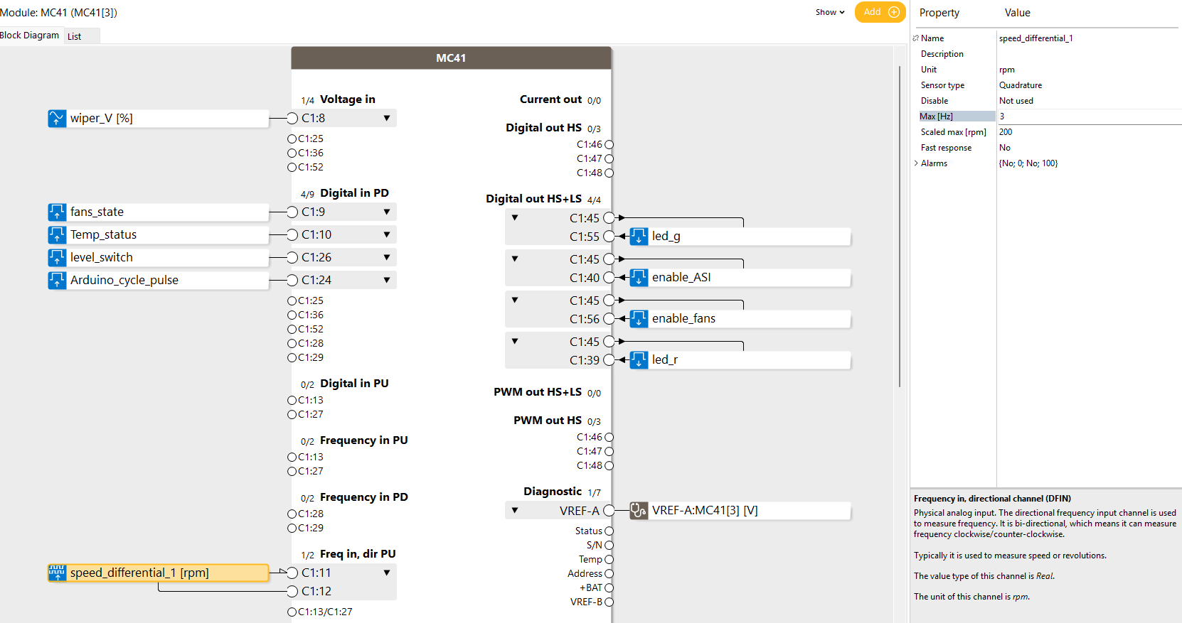
I have an MC41 module and I want to pick up the signal from a speed sensor M18-4VPFF200-Q8.
I want to measure the speed on the coupling between a motor and a torquemeter. I have a reflective sticker on the coupling, and I’m using this sensor to pick up the speed. However, when I connect the sensor, I’m reading zero on the MC41. I can see the lights on the sensor changing, which indicates the sensor is generating pulses, but the MC41 isn’t registering them.Here’s how I connected the sensor:
Sensor pin 1 (brown): 12V
Sensor pin 2 (white): GND
Sensor pin 3 (blue): C1:12 on the MC41
Sensor pin 4 (black): C1:11 on the MC41
The max speed I want to measure on the coupling is 200RPM. I calculated the max frequency as:
Thus I calculated my Max Frequency (Hz) = (Max RPM×Pulses per Revolution)/60 = (200*1)/60 = 3.33 ~ 3 Hz
Do you have any input on whether the issue might be software or hardware related?
Thanks!

Master / Expansion Different -Batt
We have a requirement to have multiple XC43 modules remotely to the master MC43FS module. Its likely they will all be powered from separate power supplies and they wont supply the same 0V for batt -ve.
Is this likely to be a problem in terms of interference etc?

PWM Output Commanded to 0, but voltage measured at Output
IQAN Tech Support,
We are looking for help with troubleshooting our "IQAN Controller, Master Unit, IQAN - MC43" Safety Controller. It is getting inputs from two Temposonics tank-level sensors in our electronic water-level system, models GB Series & RF 5th Gen input sensors. The IQAN controller is PN 20085113.
We are receiving a potential difference (voltage output) of 0.39 V from Output pin to System Ground when measured with a multimeter; however the programming software indicates that the output should be 0 V. Our known inputs and outputs are below:
|
Inputs |
Outputs |
||||
|
I!: Inclinometer |
Connector 1, Pin 26 |
0 – 5 V |
O1: High |
Connector 1, Pin 48 |
0.24 V (Pin-to-Pin) |
|
I2: AFT Level Sensor |
Connector 1, Pin 53 |
4 - 20mA |
O2: Low |
System Ground |
|
|
I3: FWD Level Sensor |
Connector 2, Pin 33 |
4 - 20mA |
***SHOULD BE = 0.0 V Output*** |
||
- The tank level sensors are bottomed-out, as there is no water in the tank.
- With no water in the tank, the IQAN is programmed to output 0% Du Cycle, yielding 0.0 gallons on the display - but there is a .39V measured.
- The lowest water level reading that the sensors could output is 120 gallons, but should read 0.0 gallons below that.
- We are needing help troubleshooting and establishing / calibrating our 0.0 baseline
Questions:
1. Why is a voltage being read at the output, when the program is indicating that it should be zero?
2. Can we create a code or loop in the program to circumvent the small output voltage?

Larger Program memory
For a long time we have been running into the limitation that the Program memory is too small for us. Is there also a view with the new MC4x to increase this in the future to 3Mb for example, this would help us enormously in adding functions that we are now forced to leave on the shelf.
MC43 Reports Vref error cannot measure
Good morning. I have and MC43 and MD4 running on a machine that is programmed in 6.08.32. I am getting random MC43 Vref B error codes along with the errors for the switches and transducers connected to that Vref.
When I record a plot graph of the MC43 diagnostic channel attached to the Vref, input voltage, and the input voltages for all the sensors, I am not able to record any change in the voltages that would indicate a Vref issue. Has anyone else ran into this issue?
Lifetime of MC43FS
We have a project that is to be used for the next 40 years. It is a functional safety system that utilises MC43FS. These modules will likely be superseded multiple times (probably due to enhancements in electronics etc) after the 20 years lifetime shown in the manual:
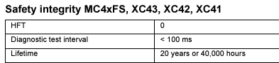
To guarantee functional safety, presumably its recommended we remove and replace the MC43FS after 20 years as described in the manual regardless if the module is working correctly? I'm trying to avoid re-assessing the system in 20 years time and fitting a safety controller available in 2045. Therefore I intend on having a brand new MC43FS available for when the system needs a replacement module in 2045.
Is the 20 years triggered as soon as the module is powered up, therefore we would need to clone the software only when we want to replace the module in 2045 (rather than installing software now and starting the 20 years timer)? Or has the module 20 years been triggered from manufacturing date on the serial number?
Customer support service by UserEcho


