
 Frequency input MC4xx
Hi,
We have installed a speed sensor (PNP, 15000Hz) onto a MC42 frequency input (pin C1:28, PD).
The problem we have is that the raw value only goes up to about 2800Hz then zero's out with no further reading and we need to get a reading up to at least 5500Hz.
I have configured the input settings to: Max HZ -> 15000 and also the Scaled Maxed-> 15000 to mach the sensor's capabilities and then use the raw reading to scale a RPM value.
We tried adjusting the sensor closer to the ring gear, but no improvement.
So I did a test to see if it might be the sensor that is faulty by connecting the sensor to a different type/brand of controller. It immediately worked and gave the correct reading constantly.
The question is now... What am I doing wrong on the IQAN side?

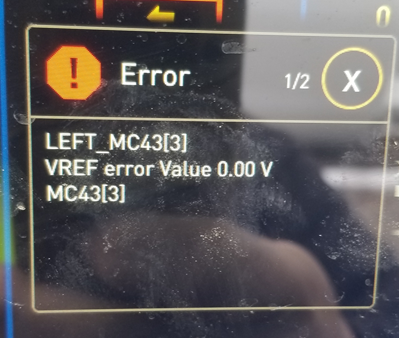
MC43 VREF error Value 0.00 V
What can be the cause of this error ?

MC43 Error Code
I have a MC43 with the following blink code 4 red, 2 yellow, 1 yellow, 1 yellow, 1 yellow. What do the 3 yellow blinks at the end mean? This happens intermittently when the module first gets power.

If it's occurring on start up, the likely causes are battery voltage exists on an output before the module powers up or a slow rise in power supply voltage. Possible causes are covered in appendix B of the instruction book.

PWM Input with frequency >500Hz
I am considering using an MC41 with PWM signals as inputs. These signals come from joystick thumbwheels on excavators made by a large multi-national OEM. My problem is the spec on the frequency of the PWM signal from the thumbwheel is 500Hz +/- 50Hz. I see the max allowable frequency from the MC4x catalog is 500Hz. Wondering if the MC41 will work with 550Hz PWM frequency input.

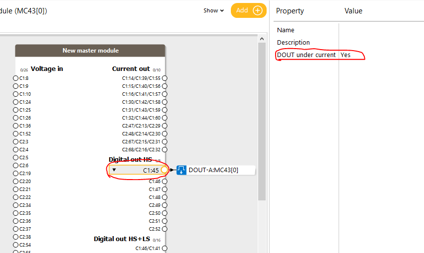
MC41FS Digital out HS disabling under current shut OFF
How this can be done? Did not find from channel properties.
You find the property on the pin in the module view.
MC41 restart after low supply voltage event
I am using MC41FS in non safety application. During cranking voltage drops, but not low enough to reset module.
Module hangs up and stays that way until power recycle. Can I restart application back up with SW?
Current output 15-85ma - Possible with MC43FS?
Hi !
One of my OEM wants to drive SAUER 90R075KAS (servo EDC, 14-85 mA) with one current output with our IQAN MC43FS.
I know that the mC43FS has a new functionnality , but I am not sure for this kind of current…. ! Please feel free to contact me if you have one solution…. Best regards.
Redundant modules
I am trying to design a system with redundant MC43s controlling the same components on their COUTs and DOUTs. Only one module would output at a time. Could this be accomplished without using relays? Can Diodes be used to prevent one backfeeding into the other? What is your suggestion?

CIN Problems sensing on MC41
I am using an IFM Efector 4-20mA 2 wire sensor on the MC41 inputs capable of sensing current. Their hookup diagram is what I expected connecting one side of the sensor to high and one side to the sensor port. The input shows a high error when I'm in a neutral state and I can confirm with an ammeter in line that I am sending 4mA to the controller. My best guess is there is too much impedance and internally it is not correcting for it so I tried adding a 5k resistor to ground externally to split the current. It now senses 3.8mA but is no longer accurate over the range.

MC43 FS Error Code When DIN Connected
We have an application which uses MC43FS module. We get an error code showing 4 x red, 2 x amber, 1 x amber, 1 x amber, 4 x amber. I have isolated the fault to one wire which is causing this error code, C1:10. The manual shows this as VIN / DIN, but we have found when connecting 24V to this pin once the module is booted, all is fine, no error code is generated. If we connect 24V to this pin and power the module on we get the error code flash up, the module shuts down, no communication is possible.
I have used a different MC43 to test and same error is generated. I have also tested by only connecting power, address tag and C1:10 and I still get the same error with the scenarios listed above. Is this a fault or is there something we are doing wrong (perhaps the allocation of pins)? Its almost as if the pin should only be a VIN and only accept 5VDC max, or perhaps its a pull up instead of pull down, is this what the error code is stating? We are unable to tell what the detailed error code is, only 'stopped critical' is listed. I will send across the video file of the error flash.
Customer support service by UserEcho


