
MC41FS Critical Errors
Hi there,
I have a critical problem with MC41-FS stand alone controllers (ie it’s not connected on Multi-Master system). FW level 6.05.18.6047
We see operation continuous for about 2 months with no error, then multiple devices on the same mahcine just stop working ll within minutes of each other (with no CAN output) and no reported/broadcast faults or recorded System Log errors. This problem is seen on multiple machines now, and a pattern is emerging of this failure. Resetting 24V power, resets the module and the error.
Clearly having a module just stop operating with no reported or logged system errors is very dangerous, as we have no means to quickly diagnose.
We have managed to collect the LED blink code when in error state: This sequence is not listed in the manuals.
Blink code
4x RED
Stop
1x AMBER
Stop
21 AMBER
Stop
2x AMBER
Stop
1x AMBER
Stop
2x AMBER
Notes:
- There are 3x MC41-FS modules per machine (all independent)
- MC41FS power supply is continuous 24V
- The machine has a "main" Multi Master system which comprises of 2x MD4-7 and 3x MC43FS modules all on MM system.
- The 3 independent MC41FS modules are connected to each MC43FS module on J1939. As far as MM system is concerned, the MC41's are another J1939 module on the common J1939 line.
- The machine MM system is operated with switched power supply (24V)
Originally I thought this was possibly a CAN bus issue, but no other IQAN modules are reporting CAN bus errors (ie the MC43 modules) as they share the same J1939.
There is one possible interaction between MC43 and MC41 module that could be contributing (depending on what the fault LED codes are from above). The MC41FS module has enabled TDA for time sync, and the MC43 is configured to send TDA PGN onto the shared J1939 continuously every 10 seconds to time sync the MC41FS. As mentioned above, the MC43 modules are connected on switched power, and the MC41 on continuous. So very night the MC43 (and full MM system) is powered down overnight). I am unsure if this is a problem, or has no effect.
Please can someone contact me to discuss this directly. I am not able to share the project file publically.
Julian

 Is -Vref and Batt- common on the MC43 module

PWM for controlling fan and coolant pump speed / schematic PWM signals
Hello everybody,
I'm working on a project, where i want to control the speed of a brushless SPAL fan and a BOSCH cooling pump via a PWM-Signal from a PARKER MC43.
However, I'm running into some issues with this.
1- First of all, I dont know how to wire the components. The fan und the pump, both have only 3 pins when it comes to PWM controlling. 24V + , 24V ground and the Sinal pin for PWM. On the MC43 i do have 2 pins per PWM signal. Could anybody show me how to wire those components? I added a unfinished schematic:
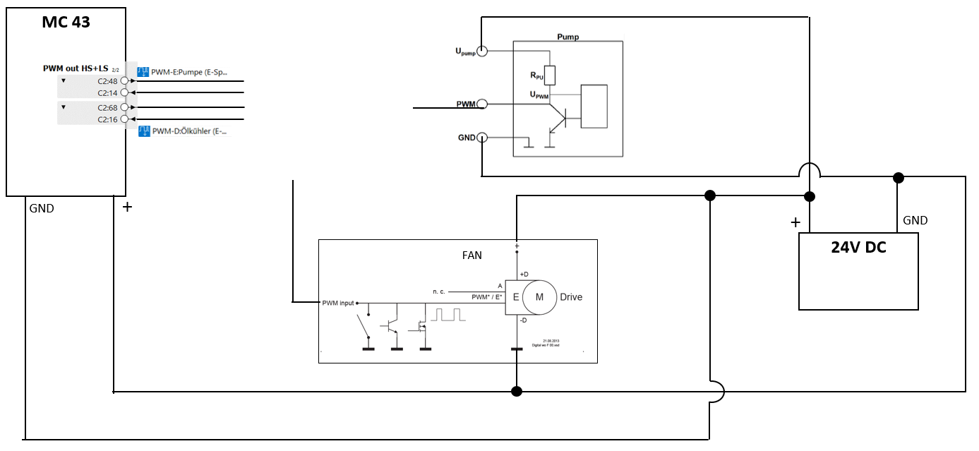
Maybe I'm missing something completly obvisous here but additions to not knowing how to wire these components, I don't understand what has to come on the PWM*/E* pin of the fan. From the picture it looks to me like this pin needs a PWM signal, wich is switched to ground. I'm not an electrical engineer but from what I understand, there is a difference between GND (-) and not having a actual potential difference. Like when something is on two pins connected to 24V DV there is no actual potential difference but there is no GND. Can anyone explaine what needs to be connected to the PWM*/E* pin of the fan?
2- The second point is, I found this threat on the Parker forum wich comes kind of close to some of my problems:
https://forum.iqan.se/en/communities/5/topics/588-pwm-as-control-signal
Where is written:
" You could use the PWM output on e.g. an XA2 or XC10 to do this, but there are a few limitations to think of The most important is the off-state leakage current on the highside driver. This is just as relevant for the case when one wants to use DOUT as a signal to another controller. If you do not pull the output to ground, you will see a voltage on the output pin that is close to +BAT level. The other will have some voltage threshold that you must be sure to be able to come below.
It is very probable that the PWM input on the other device have a pull-down resistor in the kOhm range. Then you will need to add an external pull-down resistor to load the signal. Which is tricky because this low resistance component will also have to cope with the power during the on-phase.
Another limitation you need to consider is the PWM out range. As the IQAN PWM outputs are primarily intended to drive valves, none of the outputs go all the way to 100% MR.
For modules that has undercurrent detection (like XC10), you might need to switch this off, depending on how much you load the output."
When it comes to the MC43 Module, are these problems still the same or has anything changed since that?
Because this Answer is around 5 Years old. Sorry if there are some obvious solutions to my problems, I'm still quite new in this.
MC41FS CAN Faults - Clarification please.
Hi there, I have an application with an MC41-FS connected to engine ECM and genset J1939 on CANB input. IQAN 6.05.18.6047. There are other devices on this J1939 as well such as instrumentation devices. These are all contained within a genset canopy and bolted under a train. The MC41 is used to control a single relay, thats its only function. Its not connected to any screens nor "Multi Master" system over Diagnostics A CAN for example. It does broadcast its status and other info like internal temps/status/fan speed etc using custom PGNs onto the same J1939 on CAN B.
This common J1939 CAN datalink is connected to the main group of Multi-Master controllers (MC43FSx3 and MD4-7x2). So the MC41 is indirectly linked to MC43FS on its CAN D using public J1939, just not the official Parker CAN Diagnostics link etc if you can follow that. It was not possible to use expansion modules for many reasons, MC41FS had to operate independently of the train when genset runs in isolation (not on the train) for testing etc.
There are 3 gensets on each train, therefore 3x MC41FS modules connecting to each MC43FS over 3x individual public J1939 datalinks.
I am also monitoring the J1939 using telematics, so I can see these devices operating semi real time.
Recently in service (12 October 21) all three MC41FS modules stopped communicating on CAN J1939 - all within about 20 minutes of each other. Train was in service and between stations. All other devices were fine and did not stop operating nor flag errors etc.
During monitoring , 3x MC41FS internal temps are well below 50 deg C at all times. Temperatures don’t seem a problem.
Yesterday we were able to attend the train while being serviced. I attempted to connect to the MC41FS's over J1939 CAN using IQANrun, and there was no response. We could not open genset to check lamp status as this is a sealed unit. So we only had the option to power down and on again. This cleared the issue and all the modules CAN network came back online again.
- I have read the article regarding the No Contact CAN errors and possible causes for this. There could be many reasons why this module may have problems, but the unit has been in service since July 2021 which is 3 months now. No other device has locked up (ie the MC43s modules are connected to the same J1939 datalink
- Looking at the MC41FS System Logs, there were historical errors with the Relay (Critical Error) but these were in July 2021, and since this time, there have been 5-6 System Started log events, meaning to me that the MC41FS was powered down and back again as part of battery isolation etc. This was the period when the genset was being commissioned and power supply and wiring issues were probably encountered regularly
- There were no System Errors recorded in the log folders since August. Nothing at the time of the CAN Buss Off issue in service
- The MC41FS has TDA enabled, so the MC43FS is used to send TDA PGN to the MC41FS over J1939 for date time alignment
Questions:
- The article on No Contact references that CAN errors are accumulative before the CAN goes into Buss OFF status. Are CAN faults / issues cleared on reset? I would have thought so. Would this have been accumulative even though there were resets?
- With reference to 2x nodes sending the same CAN Identifier: Does this refer to the entire 29Bit header ID or the PGN only? Ie I see no problem if two nodes send the same PGN, provided they are not the same Source Address?
- Has there been any helpful updates in recent IQAN FW releases after this 6.05.18 version that will help re-set the CAN if there is a Bus Off event?
Its very hard to troubleshoot this situation from afar I know, and the only thing I can possibly consider changing is the application of the MC41FS or the FW or both.
Does anyone have any helpful comments/suggestions?
Thanks
Julian

is there a real time clock input on the MC43? I cant find one in the manual.
Negative PWM
Hi All,
We have a motor that requires a PWM negative signal. Using an MC42, anyone ever done this? if so, how?

Controller for motor, about 2000hz needed
i need help with choosing a controller to operate at abut 2000 hz for motor control. i currently have a MC43 and it doesnt seem to have the speed required for what i am doing. i get about 100hz
Could someone recommend something?
Can't connect to MC42FS
I am having problems connecting to a MC42FS.The PLC worked fine last friday but when trying to upload some weekend changes this morning the PLC suddenly stops working. On the first programing attempt after power-on the programing process stops at "stopping applications" followed by a "no handshake replay". Trying to program the PLC after will only result in a "no handshake replay". If connecting to the PLC after cycling the power with IQAN run i get the following error. "There is no valid application in the target module. Error code R4:2 1:1:1 (Int.diag error(Backending?)) MS42FS[NI address tag] (FW version 6.04.4) i have tried multiple times with and without the ID-tag, but nothing changes. Any ideas on how to get it working again?

venorn
How is the performance proportional pressure control devices, such as a Parker RE06 without on board electronics, using Parker MC4* current output channel? The Parker industrial driver, PCD, uses a 10kHz PWM frequency to drive an RE06 coil. The Parker MC4* has a current output PWM frequency limit of 500 Hz. I have driven an RE06 coil using Iqan products in the past without noticeable performance issues, but wanted to see if others have done the same.
Thanks

IQAN M43 Error Code: Manual says contact Parker
4 red flashes, followed by a yellow flash sequence of 2-2-1-3
This continues to happen when trying to start the engine of the machine. As if maybe the battery voltage is going too low momentarily.
Once in this state, the IQAN module cannot be communicated with using IQANRun 5 and is not operational until powered off then on, but will deliver the above flash sequence.
Any help would be appreciated.

Please the footnote related to a 4:2 blink code in appendix B of the instruction book. This is likely a fault caused by extreme voltage caused by cranking.
Customer support service by UserEcho


