
 DOUT voltage when not enabled
Hello,
I am having some trouble with the Parker MC41. I have a display button on another MD4 that enables / disabled the output on Pin 45 (DOUT-HS). I am seeing a proper system voltage of 12.26V when the value is true, however when I set it to false Pin 45 goes to 11.68V. Is this normal behavior? Should I have some sort of diode in there to get the desired on/off I am expecting?
Thank you.
VIN combined with CIN
The MC43FS manual states that:
Note that for the MC4xFS, a voltage input combined with a current loop input is not
sufficiently diverse if the two signals are following each, the higher gain error has to be
considered.
Does this mean a single sensor measuring voltage (single output from the sensor) into a VIN and also current from the ground of the single sensor into a CIN? Is this what is defined as combined? ie. singe sensor, 2 inputs.
We are planning on using a single voltage output sensor providing a single VIN, and a separate sensor with 4-20mA signal output into a dedicated single CIN. Notes in the manual suggests we cannot do this because they are not crossed, even though they are independent sensors, different technologies and have separate wiring. What's the restriction and why, is it because it uses the same AD converters in the module? The pins are not shared (cannot be configured as voltage inputs or current inputs) so unsure of the reasons behind this.
Just looking for clarification really as the statement seems to suggest we may be able to if....'the higher gain error has to be
considered'? Both the sensors we are planning on using are not crossed (signal outputs increase as pressure rises, one voltage the other current).
Thanks!

DOUT LS issue with LED
Greetings,
I have 4 LEDs each connected to a DOUT LS channel on an MC43.
The issue I have is they each turn on faintly even when the output is off.
Once the DOUT is on the light appears brighter.
The LEDS themselves are 12V LEDs like this one (though each is a different color):
https://www.factorymation.com/PDA-B12V-B
I don't currently have a Current Limiting Resistor inline, would not having that cause this sort of behavior?
Or is there something else I am missing about operating LEDs off the DOUT channels?

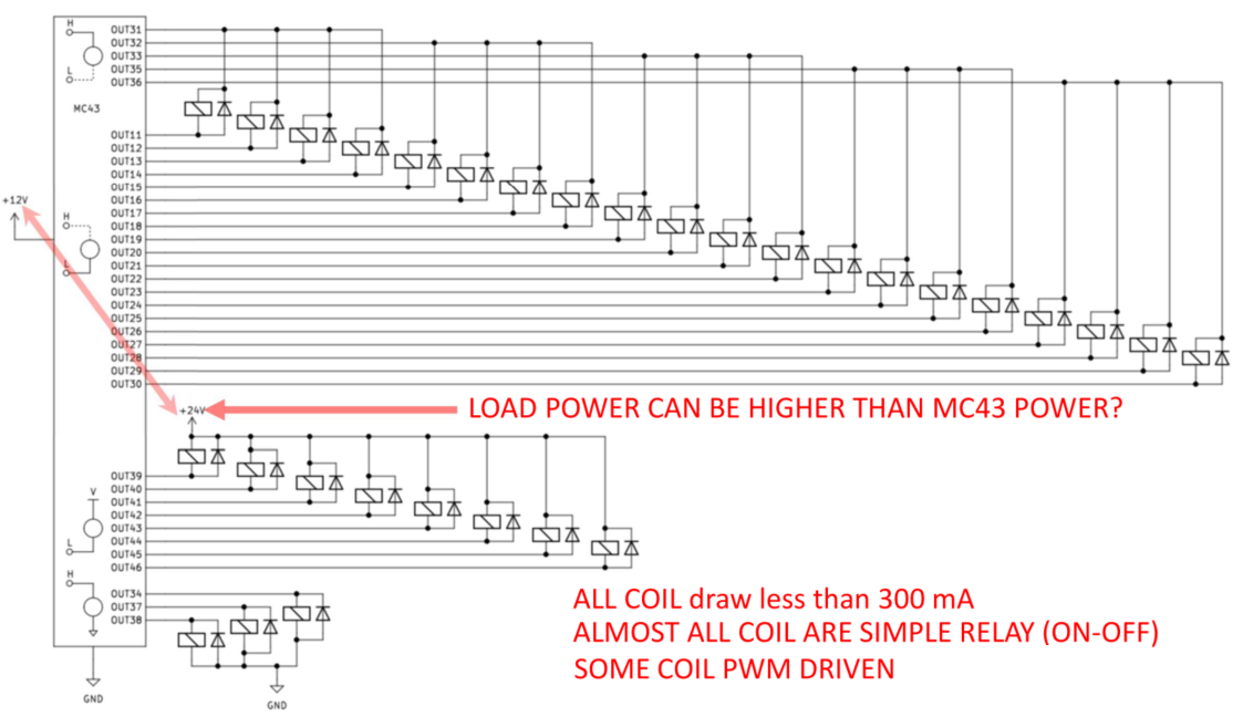
Digital out low side outputs
Is this MC43 output configuration is correct?
Can we power a load at higher voltage than the MC43 power for output 30 to output 46?

Fault Capacity of -VREF
In the IQAN MC4x/XC4x instruction book on page 67, it is recommended that sensors requiring a supply of more than 5V have their returns connected to -VREF instead of chassis ground. I understand the reason for doing this is to minimise sensor error, however, if the sensor supply is shorted to -VREF there will be a large fault current through the -VREF pin. What is the fault current handling capability of a -VREF pin? Furthermore, if this pin is not capable of handling high fault current for the time it takes for a typical thermal circuit breaker to trip, would powering the sensor from a digital output with current limiting be a preferred option?

Can PWM outputs be programmed to send 0-10Vdc signal?
I have been doing some research and configuring a CANopen module to send a 0-10Vdc signal to run a prop valve. I have now been told that a PMW output on the MC4x and XC4x can be programmed to output 0-10Vdc. I wanted to confirm that is correct as I have seen in the forum that you are unable to send out that signal type.
Motor control with MC41 in full bridge mode
What is the best way connect motor in full bridge mode to MC41?
Controlling 9V/2.7A prop valve with MC4X
Has anyone tried to control a D1FBE01HC0NMWO (9V/2.7A spool) with a PWMOUT, if so what is the performance like? The rating for COUT is 2.5A so I will have to utilize the PWMOUT HS. I have read that COUTs allow the best performance with solenoid.

PWM Output - Doesn't Work with Low Current Load
I am trying to us a PWM HS Output on an MC4x to drive a signal needed for a PWM fan. I will get an open load when I try to drive it directly, and even with disabling the open load check it still will not work. The output just stays at 12v.
If I add a 1k resistor from the PWM output to ground, everything works as it should. But now the issue I have is with no power to the MC4x, I have some leakage voltage in the range of 50ma which will draw the battery down.
Is this a software or hardware issue that will not allow me to use this PWM output to drive this fan directly??
My work around is using a relay to make and brake the resistor to ground when the MC4x is powered. But this is not a great solution, and would like to see if this is just a software issue that could be fixed.

MC4x parallel HS output usage
When an MC4x DOUT HS is wired in parallel, are you able to drive a single output as long as the over current limit is not met? What I driving at is activating both outputs initially, and deactivating one later.
Customer support service by UserEcho


