
 How to Perform Short to Ground and Short to Battery Tests on Parker ECU (like MC43FS)?
Hello,
I am working with a Parker ECU (MC43FS), and I need to test for short to ground and short to battery faults on specific pins. Could you please provide detailed instructions or best practices for performing these tests safely? Specifically, I am interested in:
- How to safely simulate a short to ground on the pin and verify the system's response.
- How to simulate a short to battery and what actions I should take to test the system's reaction.
- Any recommendations for multimeter settings or test equipment to use during these tests.
- Expected behaviors or diagnostic codes (e.g., LED blink codes or error logs) that the ECU will produce during these failure scenarios.
- Any precautions or potential risks I should be aware of during testing.
Thank you for your assistance!
Best regards,
Sayan Biswas

Safety COUTs as DOUTs
We have a project that requires control of multiple cylinders, each cylinder is connected to a double acting valve, 2 separate coils, one for each cylinder movement (in/out). These outputs must be safety in our application.
Reading the instruction manual for the DOUTs on MC43FS, it states we must use only one DOUT HS and one DOUT LS per output when its being used in a safety application, so the controller can switch the valve off by either side in event of a fault. Therefore I have concluded we can only have 5 DOUT safety per MC43FS. Or in other words, 2.5 cylinder valve controls.
Can I instead use COUT, and therefore each cylinder function can be driven by a complete COUT A? For example, i can technically connect 10 cylinders, in/out, i.e. 20 valves? I would have to ensure the current does not exceed the limitations of the groups, but does having the shared COUT + affect the safety aspect of a COUT? There is a note saying all COUTs are safety, and nothing about sharing pins like there is under DOUT so I guess I can overcome my issue of limited DOUTs for safety?
I guess if there was a function other than driving a component in a direction it would not be possible, as you can only drive a COUT in either + or - direction, i.e. not both if you has different valves to energise, which could be at the same time.
Also it explicitly states no diodes on a coil connected to COUT (I guess for regulation), does this still apply if I'm using COUTs digitally, ramping from 0-100% and 100-0%? Would the collapsing digital coil cause damage to the COUT driver?

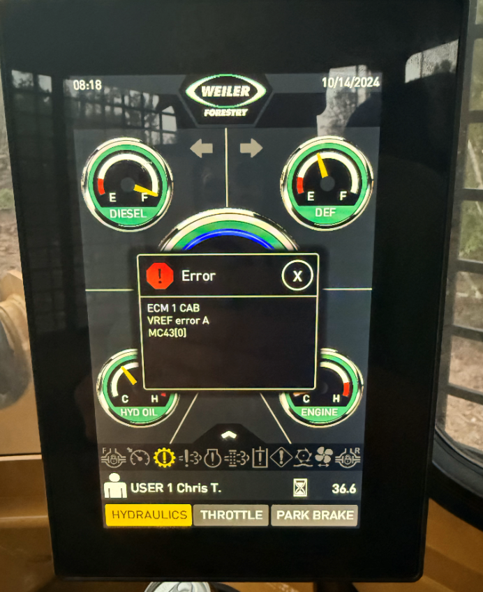
What causes error code VREF error A on MC43?
How does an open load error effect the operation of a PWM HS+LS output.
I am testing logic with a MC43 and using a PWM HS+LS output.
In the system we are using both sides of the output (+ and -) to drive two individual devices.
Both should never operate at the same time.
To simulate one of the device not operating, we unplug one of the solenoids.
With logic, this automatically causes the other side of the output to now function.
Basically, if the + side fails, it should switch to the - side and operate.
We are getting an open load error on the output with one of the solenoids unplugged and it does not allow us to operate the other solenoid on the PWM HS+LS output.
Is the output designed to shut off both sides if one side detects open load or should the other side work if one side detects open load?
As an example:
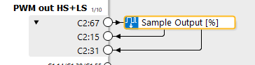
If the solenoid between C2:67 and C2:15 is unplugged, but the solenoid between C2:67 and C2:31 is plugged in and fully operational, should we be able to command it with an input signal of -100?

Input Ranges for PWM and Accuracy
Is the MC4X PWM Input able to monitor frequency ranges outside of it's normal function like 1000 Hz and if so what would the effects be with the resolution of the readings from the MC4X?

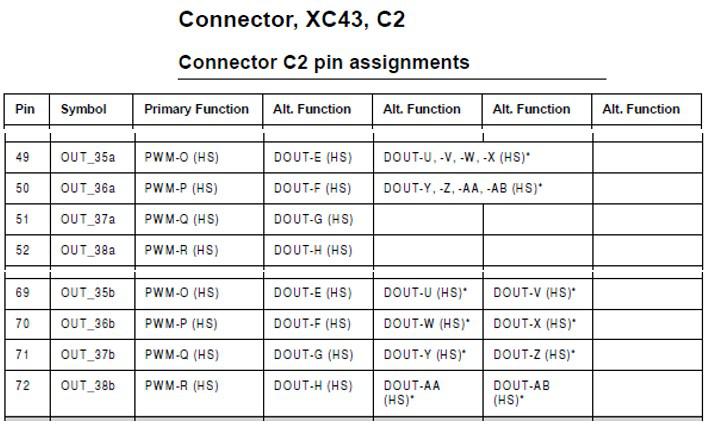
OUT pins a/b
Apologize that I have to use the wired topic. Otherwise the submit window will go to search result and not be able to submit my question.
Why there are OUT_xxa and OUT_xxb? Are there any relationship between them? Have to use them in pairs?
Open Load status not resetting in all situations
I am having a problem with the open load detection on a COUT on am MC43FS
- I am running IQANdesign 5.03.14.5040
- The manual indicates that the output detects open load two different ways which may be true, but the controller responds in three different ways.
- When the output is off, if the load is disconnected, the controller will set the open load status to TRUE, when the load is reconnected, the controller will set the open load status to FALSE and allow normal operation.
- When the output is on and passing some normal current, if the load is disconnected the controller will set the open load status to TRUE and turn off the output, if the load is reconnected, the open load status remains FALSE, and the output remains off until the command is set to zero. Setting the command to zero causes the controller to reset the open load status to FALSE, after which the output will respond to a normal current command.
- When the output is on, AND some fault causes the resistance of the load to increase such that less than 50% of the commanded current can be pushed through the load, the controller will, set the open load status to TRUE and turn off the output. Unfortunately commanding the output to zero does not cause the controller to reset the open load status to FALSE. This acts like the open load status is latched to TRUE if it was tripped by “extreme saturation”
- It is my belief the third response is a bug in MC43FS because, a MC2 running IQANdesign 4.07.7.4605 works as expected I.E. commanding the current to zero would reset the open load status to FALSE Such that the controller could lower the current and try again.

More (HS)* (LS)* MC43FS
Hi,
I have a applciation with alots of safety control Dout.
Like i could read a the page 97 and 99 of the instruction book manuel of the MC43FS.
We can have 5 Dout.
In safety function we need to combine one HS and one LS pin to a output.
In Dout i have acces to 5 direcly and would need 6.
I would like to know if it is possible to use the pin C2:71 HS and combine with a other LS for example C2:16 ?
Else my other solution would be to use Cout as a ON/OFF signal output unidirectional.
Thanks
Dart

Using a resistance output sensor on MC43
A customer has purchased a resistance output level sensor (240-33 ohms). I have tried to find more information regarding converting this to a VIN, but couldn't find too much. I am wondering what else needs to be done other than incorporating a voltage divider in their circuit.

MC42 supply
Hi
I have a project MC42 for embedded Simulink models which is only possible in MC4x. But I got a information that Parker do not produce MC42 module anymore. Is that true ? If yes, Have any solution for simulink models in IQAN ?
Customer support service by UserEcho


