
 Does Ixxat simplyCAN USB-CAN adapater should work with IQAN system?
Hi,
I'm currently shopping for a USB-CAN adapter.
Looking at this thread : https://forum.iqan.se/knowledge-bases/2/articles/231-usb-to-can-interfaces , I went to Ixxat website because I used it in the past with IQAN system and it was working really fine.
I know I could go with the regular "USB-to-CAN V2 compact" (https://www.hms-networks.com/p/1-01-0281-11001-ixxat-usb-to-can-v2-compact), but I came across the "simplyCAN" which is around half the price :
https://www.hms-networks.com/p/1-01-0001-12001-ixxat-simplycan
Does anybody tried the Ixxat simplyCAN and confirmed it works OK with a IQAN system?
Have a good day!
Sam

Driving PVEM Danfoss With IQAN MC43
Hi folks,
Does anyone here have experience with controlling a Danfoss PVEM valve with IQAN?
Danfoss literature is rather scarce, and I am working with a legacy machine, and trying to upgrade the controllers.
What should the signal be going from the MC43 to the PVEM?
Thanks,

connecting to iqan system with a cat comm adapter 3 for software update
We have a IQAN R7 software app on our computer. We are trying to communicate with a IQAN software on a Weiler brand machine. It has a CAT ET port that we are supposed to connect to the machine with via a CAT Comm adapter 3. When I go to connect, selecting CAN on the connection page, it gives a error code E126 Unable to load CA3rp32.dll. Please update RP1210 driver to a 64-bit version. I dont know that we have that option to do a RP1210 update.

0-10 V output from an XC4x
XC43 does not have a 0-10V output. I need it for a command signal to another module. What is the best way to do this? PWM? COUT with resister? Thanks!

molex connector cable
What cable fits the molex connector best? i have tried several cables but somehow the shield is always to thick

Obsolete MC1606
Good Afternoon, All,
I am working on an old Iqan transmission controller for a company that has since gone defunct.
Do any of the old timers around here know anything about an IQAN MC1606?
Does anyone know how I would go about cloning the project so that I can install it on another used module?
Any information on this obsolete controller would be appreciated.

Electrical schematics
Good afternoon.
Some years ago there was available the electrical schematics such as for example IQAN-MD3_uk_electrical_schematic.
Are these still available as I am after a copy of both pdf and dwg for:
IQAN MD4 electrical schematic
IQAN MD4 electrical system schematic
IQAN XA2 electrical schematic
IQAN LC5 electrical schematic

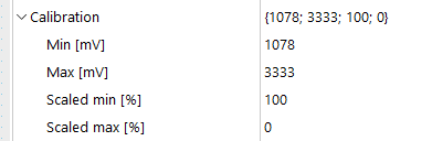
Scaling resistance to voltage
I am trying to calibrate a level sensor that has a resistance output of 240 ohms (empty) to 33 ohms (full). The calibration below was what the setup is currently, but I am getting a high error on the VIN input. I am looking to fix the min and max, but I am unsure of how to scale this to voltage. I am getting a raw value of ~4999 at full.

Customer support service by UserEcho


