
 Differential Analog Sensor Signal
I am looking for a way to use a shunt style current sensor that has a differential analog output with an IQAN module. Does anyone have suggestions? https://riedon.com/resistors/view/ssa Riedon-Smart-Current-Sensor.pdf

Powering down modules in runtime
I have to modify my system and add 2 expansion (or masters if necessary) to meet safety standards. Only 1 module can be powered at a time. Is there a way to do so without having errors every time one is powered down?

Serial numbers from clone
If you make a clone, can you read the serial numbers of the hardware where the clone is retracted from? In the clone file somewhere I mean.
Thanks,
Marcel

IQAN ST sensor current consumption
Is 5 - 7.5 uA correct for current consumption? or is that a typo in the data sheet?

PT100 Temperature Sensors
Can any tell me if its possible to use a PT100 Type S temperature sensor on a voltage input in a MC43?

4-20ma customer PLC supplied signal for monitoring (XC43)
I am designing a new system where the customer has to send me a 2 wire 4-20ma signal to monitor. I can add a resistor to convert it to a voltage input, but I would prefer not to. The manual shows a 3 wire hook up, if I were to not use the Vref pin, would this still work? I am not concerned about the output getting out of scale, and when we do a startup I can calibrate it to the PLC actual range...
Should this work?


 Industrial Style IQAN Module for Electrical Cabinet
We've used IQAN modules extensively in our equipment and we've always mounted the modules in an electrical cabinet. We prefer the entire IQAN system to other PLCs that would normally be used in a cabinet, but we could really benefit from an IQAN module that was more industrial style, i.e. that it would have screw terminals that were easy to rearrange, add, remove, etc.
Has anything like this been considered before? Anyone else with this need?

IQAN-MG units product no. 5010001
Could you advise if there is a replacement for the 5010001 ?
I have a defective module on my SMV SC4542 TA5 and I can not find a replcement
could you assist me ?
PWM MR Values
I am trying to control a valve without over speeding the pump. What would the MR values need to be? Does 100% command at a 100% Max MR value equate to the source voltage, in this case 24VDC? See coil characteristics below.
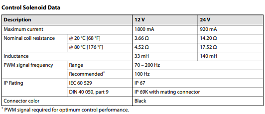

If you have an important function like this you should not use PWM outputs from IQAN, you should use COUT. The PWM outputs from IQAN are not temperature compensated and you will see consistency / repeatability problems. When you use the current output channels with IQAN you will be able to set minimum and maximum current requirements easily and the current will compensate for changes in coil resistance.
Customer support service by UserEcho


