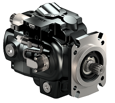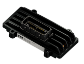
 CAN connection between MD3 and MC31
Hey there!
I'm using a MD3 and a MC31 on my application. I'm transfering the application through an USB-to-CAN interface (KVASER - LEAF LIGHT). I'm using the same cable to transfer the application simultaneously to MD3 and MC31. The transfer completes greatly, I can even use the Measure feature on IQANDesign to get signals from them both. But, between them, the MD3 can't see the MC31 (No contact error), as well as MC31 can't see the MD3. Can anyone help me? I can send pictures of the connection and the error that is occurring.

MC41 losing CAN comms
We are using a MD4-7 and x2 MC41's on some of our machines (we actually wanted to use only x1 MC42 for these jobs but we are still waiting for the parts to arrive and have deadlines to meet so we are just using what we have available to get the job done)
But last night we started testing the machine and went through all of the procedures and functionality when all of a sudden an error appeared on the display telling me that one of the MC41 controller lost comms, but the other one was still fine and giving readings... So the 1st thing we tried to resolve this was typically switching the machine off and on, but this time there was no CAN comms at all.
We went though the wiring harness and made sure that everything was correct and the wiring was all good, so we then went and replaced both these controllers with new MC41's we had in stock, we plugged it in uploaded the software and the system was happy again with the new controllers and it is still working fine at this moment... So I took the 2 faulty MC41's to my office and connected it all together to try and diagnose the issue.
Each time I tried uploading software (using IQANDESIGN 5.01 via ethernet) it kept on warning me about the incomplete system and that only the MD4-7 will be updated.
Eventually we switched from CAN-A to CAN-B only on the MC41's. but upon each attempt to upload the software, the same "incomplete system" warning appeared.
So I just left it for a while and a few minutes later decided to just try again uploading once more. Well it worked all of a sudden and that is also a big problem, because I didn't change anything where I could say " there, that was the problem".
This is worrying us a bit, because we have no idea why this happened in the first place and secondly these machines are going to the middle of Africa... So this sort of thing must not happen at all!
I have only been using MD4's and MD3's with XA2's in the past without any problems at all, these are our first machines using the MC4x family and this is also the 1st time that I encountered any issues like this on IQAN.
Have anyone else experienced this before? I have no idea why it failed or why it started to work again and this is definitely not the correct answer to give the person asking this question when there are deadlines to meet.
The other thing to mention also is the LED's on the controllers which blinked bright yellow 3 times then blinked dimmed yellow 3 times while it was not communicating. which also does not correspond with these fault codes in the manual. There was no RED LED blinking at all.

Pump Control Module for eP2 piston pumps
Our colleagues at Parker in Germany has released a Pump Control Module based on the IQAN-MC41, for the P2 pump series.


The Pump Control Module (PCM) is a pre-programmed stand-alone module that acts as a dedicated pump controller with either analog or J1939 commands.
As it is based on an IQAN module, adjustments and measure is available via IQANrun over CAN.
To ease integration in an IQAN system, an IQANdesign 5 plug-in module implementing the J1939 interface to the module is being developed.
For more info, see:
http://solutions.parker.com/ep2

 MD4 10" screen
Does anyone know how the 10" version of the MD4 is coming along. The last information I had was the unit was not released for production yet due to screen fogging issues. I hope that is resolved as I may well have an application for the unit.
Is the unit available for sale?

 MD4 user inputs
I have tried - Grayhill - Graf-Syteco and powerkey so far who do have keypads but they do not have a size or shape currently in production that fits nicely alongside the MD4 (7").
Does anyone have any ideas?

Great Job Rotating the MD3-M15 screen 45 degrees to correct polarization issue. Our customers are pleased.

 usb Ethernet adapter for MD4
Could I add a USB port and a USB to Ethernet adapter so they can continue connecting with USB?
Does anyone have a better workaround?

MD4 Temperature Test
Last monday, we did MD4 temperature test. MD4 waited at -33°C for 4 hours in a closed enviroment. After 4 hours, Power on MD4 7" touch panel and We tested digital in, digital out, canbus channel, touch screen. Resault we are fine. We didnt have a problem. My hand just froze when testing :)

 Analog Input - Temperature Sensor
The question is if any of you have used a temperature sensor in the analog input of a MD4-7? Was it PTC or NTC? Because in pdf only talks about connect a PTC sensor with a pull-up resistor. Kind regards. Diego.

 IP camera with external 12/24VDC supply.
Do anyone have a good suggestion of a IP camera for MD4 that have external 12 or 24VDC power supply? Most of the cameras I've seen only have POE and a POE injector just ad up a lot of cost.
Of course rugged design for mobile application would also be a benefit.
Regards / Niklas
Customer support service by UserEcho


