Connect PC to MD3 by G1 modem
Hi all,
I connected an old G1 modem to a MD3.
The connection between them is OK, the modem receive and send SMS.
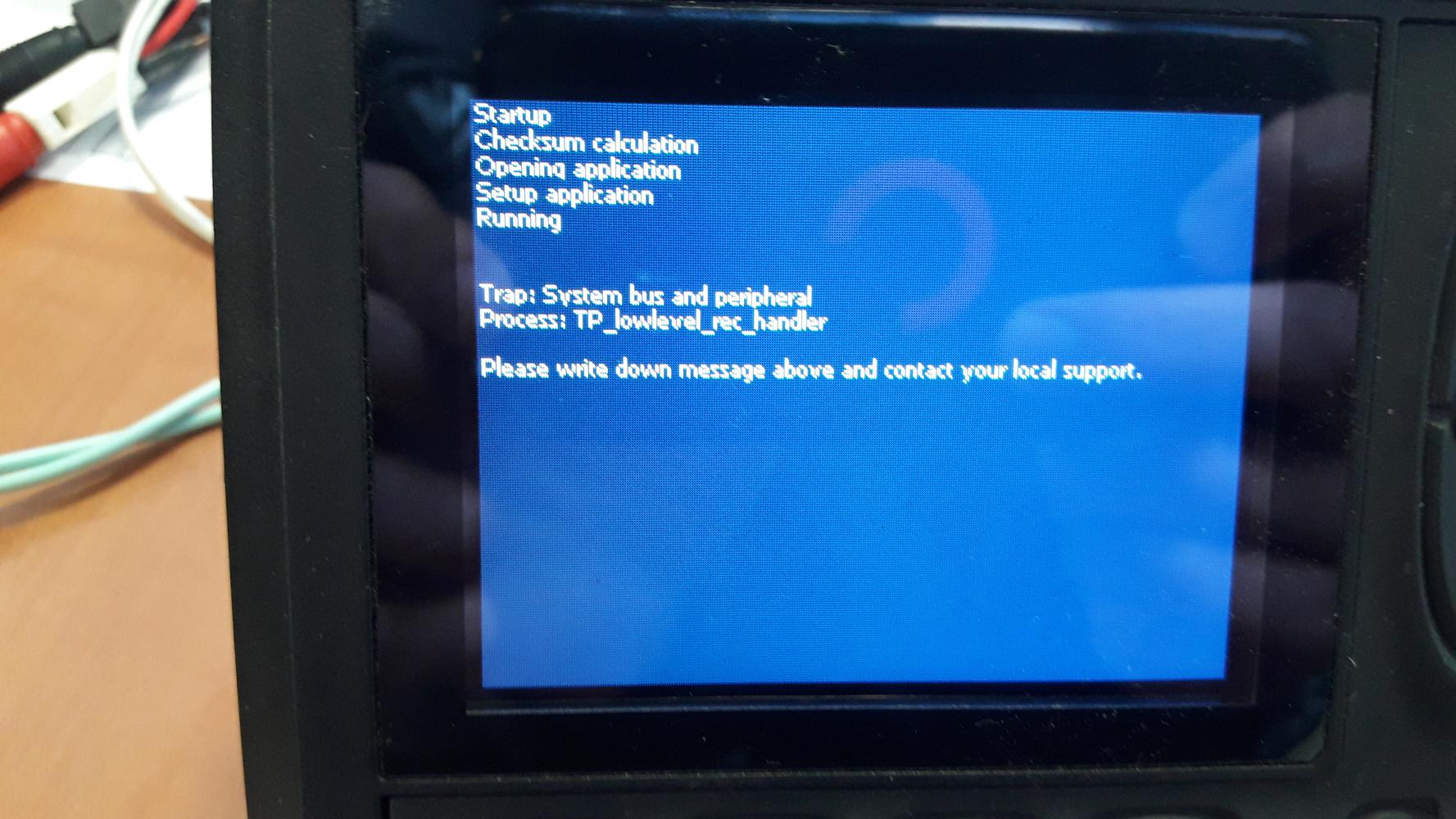
But when I connect my laptop with IQANRun2 to the system (MD3+G1) I have a Blue Screen.

Do you think the modem I'm using can cause the problem if it send voice instead of data?(56k USB Modem USRobotics)

 Resistive Fuel Sending Unit into MC43?
Quick question on fuel senders.
The kind we have included with our fuel tank is in fact not a current out, but resistive fuel sender. That is, 1 terminal is connected to ground and 1 terminal is the signal wire with varying resistance based on fuel level.
Is there any way that the MC43 can read this?

 MC43 DOUT HS + LS
We are having some odd things happening with a system designed using DOUT HS + LS outputs.
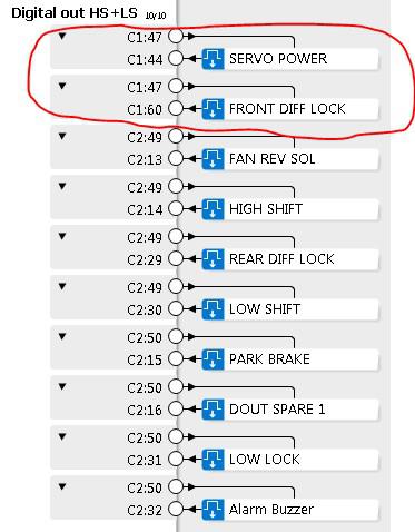
We will start with the first group circled in Red below, but are having the same issues with the other HS + LS groups. You can also reference the schematic below for the HS + LS wiring for “Servo Power” and Front “Diff Lock”. This is with "DOUT under current detection" on.
- If Servo Power and Front Diff Lock both are False and we disconnect one or the other, the corresponding function will show “open load” as expected.
- If Servo Power is True and Front Diff Lock is False, and we disconnect either one, the corresponding function will show “open load” as expected.
- If Servo Power is False and Front Diff Lock is True and we disconnect Servo Power, no “open load” is shown
- If Servo Power is False and Front Diff Lock is True and we disconnect Front Diff Lock, both show “open load”
- If Servo Power is True and Front Diff Lock is True and we disconnect either one, no “open load” is shown
If we turn "DOUT under current detection" off, the outputs will behave how we understand they are supposed to. Although, doing so removes open load detection when the output is true.


 Using MC4x to drive Pulsar 75 hz coils (retrofit of coils)
The instruction book recommends NOT using an MC4x for 33/75 hz Pulsar coils.
I have an application where we are using an MC43 driving PF coils, and the customer is asking for a retrofit to 75hz pulsars, for common coils with other equipment. Is it possible to add external diodes/etc and drive these coils, or will we have to replace the controller?

 MC43 DOUT HS&LS max load per group
What are the group numbers for these outputs? The manual doesn't list them in appendix A?

 Invalid application MC43
Hello,
This happens in a system with just an MC43, and no other connection than Ethernet.
Same hardware and software without problems on previous machines.
After successfully sent the project to the system (through Ethernet, and from IQAN Run or from IQAN Design ), when trying to go online the following screen appears:
(from IQANDesign 5 Latest version, after trying to go online)
(from IQANRun 5.01, after trying to get system info,or enter Adjust, or whatever)
It seems the module lights blink the following way:
4xRed,
2xYellow + 2xYellow + 1xYellow + 3xYellow
All short blinks...probably.
Any hint?
Thanks a lot.

 LOG ERROR
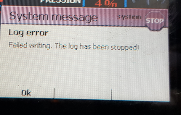
.One of my customer receive this message , this is a MD3. I dont know why ?


 md3 premature failure in humidity?
I have a customer who has had 2 MD3's fail in 2 years. They are in Puerto Rico and they think this is due to the humidity. Has anyone else seen this? I personally have not seen the MD3 that they are replacing so I don't know if it is beat up or user error.

 3 wire 0-20mA sensor input on MC4x
The installation manual states an example for a 2 wire 0-20mA input into the controller, but there is no reference to a 3 wire input. Are these supported? I'm assuming it will be the same connections just the sensor ground (which does not include the signal) will go to chassis or vref -ve? Can anyone confirm?

 L90LS controller
l have an L90LS valve with proportional soleniods and would like to use a Joystick to operate which is the best choice out of parker range
Customer support service by UserEcho


