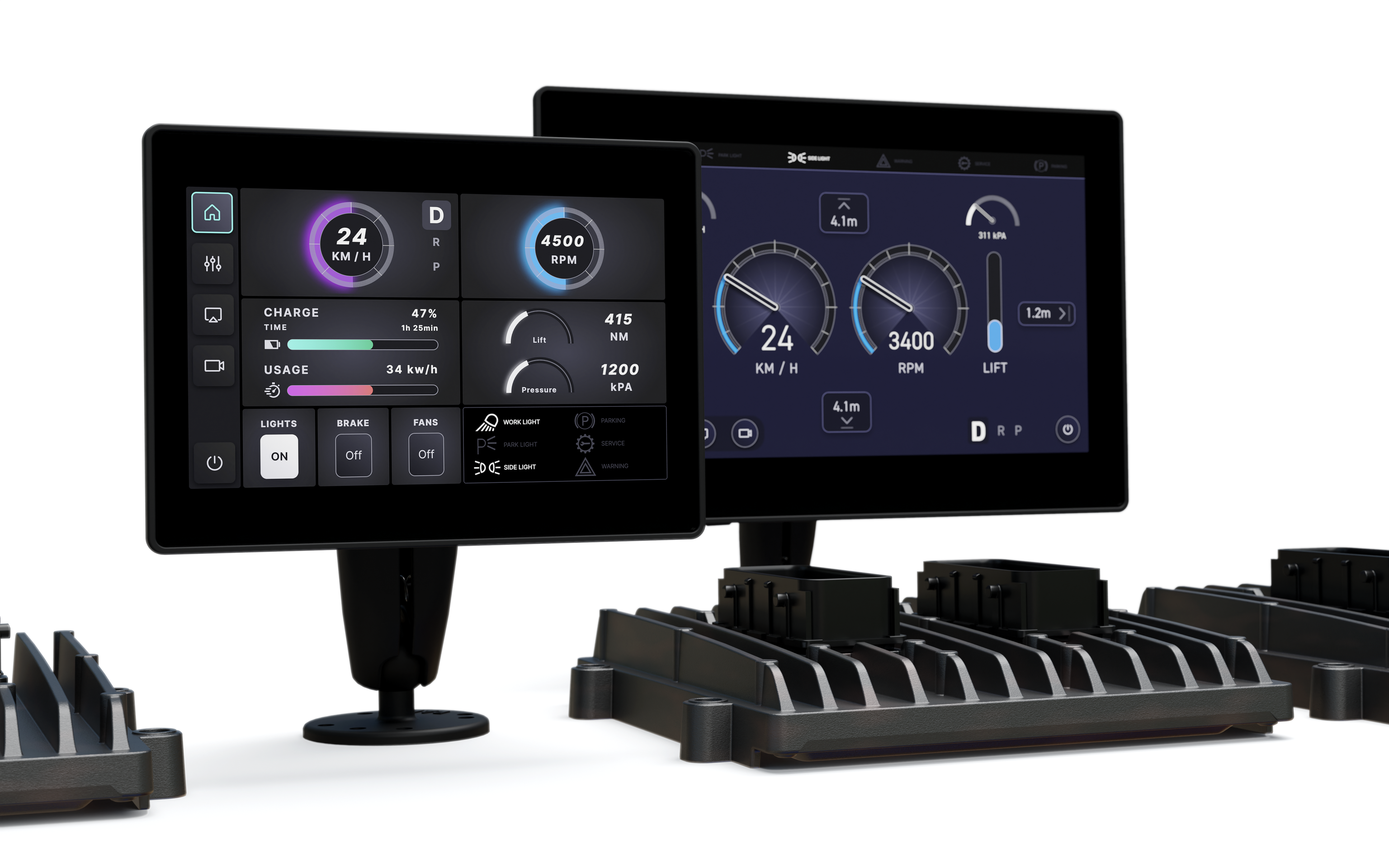
IQAN-MD5 - release of 5" and 8"
We have now released the first two variants in the IQAN-MD5 family, the 5" and the 8" variants.
You'll need IQANdesign 7.02 to use these, which also is available.

Product information are available on parker.com.

The IQAN-MD4 platform will continue to be supported alongside the newly introduced IQAN-MD5 platform. Our standard End-Of-Life (EOL) process for products involves a notification given three years prior to the Last Time Buy (LTB) opportunity, followed by a period that allows for last-time purchases, with the last delivery occurring approximately two years after the LTB date.
In the long term the IQAN-MD5 platform will live longer and is a better choice for you when planning your platform moving forward.

 MD4 day/night mode.
Would be nice for MD4 displays to have day/night mode where background and text properties would change without the need of creating extra layers.

 Coil Suppression on MC4x Outputs
Hardware Question:
In the Documentation for the MC4x family of controllers - it says in many places to use diodes for external coil suppression, for example when driving a relay with the Digital Out HS driver from the MC4x.
A relay that I have specific to my application requires (highly recommends) the use of varistor coil suppression, which is less "harsh" on the relay device during transients. The specification requests a clamping voltage of 3x the coil voltage, i.e. 36Vdc for a 12Vdc relay coil.
Are there any adverse affects of using a varistor instead of a diode for coil suppression?
Perhaps this could be also compatible with the hardware design of the MC4x series of controllers?
(Hint: I already have tested this configuration on my system to many thousands of cycles under load with no discernible affect on system operation or relay operation)

 MC43FS - Are there any plans to upgrade RAM/Flash on this module ?
This module supports alot of IO and 5 x CAN. Very simple functions to serve all of the IO and CAN easily burn the available resources and I am wondering if there are any upgrade plans ?

 Speaker

 MC41 blink 4R – 1Y – 12Y – 3Y – 1Y – 1Y
Hi all I hope someone can help me here,
We tried to update an MC41 via Design and it got stuck at the end of the "Rebooting" phase,
The blinking pattern on the module was : 4R – 1Y – 12Y – 3Y – 1Y – 1Y, and we could not reconnect to it.
Since the unit is rush, we shipped a new MC41 to our shop. After testing they realised some parameters weren't ok, so they went ahead and pushed Settings via Run.
Exact same thing happened : stuck with a full green bar on "rebooting" and pattern that our road guy saw (no video) was "4R - 13Y" but it might very well be the same
Is some of you have seen it before and might know how to resuscitate them ?
Thank you,

MC4x-M24 serial production
The new -M24 versions are now in serial production:
|
Upgraded Product |
New part number |
|
IQAN-MC41-M24 |
20085211 |
|
IQAN-MC42-M24 |
20085212 |
|
IQAN-MC43-M24 |
20085213 |
|
IQAN-MC41FS-M24 |
20085221 |
|
IQAN-MC42FS-M24 |
20085222 |
|
IQAN-MC43FS-M24 |
20085223 |
|
IQAN-XC41-M24 |
20085231 |
|
IQAN-XC42-M24 |
20085232 |
|
IQAN-XC43-M24 |
20085233 |
See updated catalogs:
IQAN-MC4x_brochure_HY33-8413-UK.pdf
IQAN-XC4x_brochure_MSG17-8417-UK.pdf
Requires IQANdesign version 7.03, see Version 7.03 released / Software / IQAN

Good question!
The -M24 versions will be the ones that will remain.
The classic versions will, due to age of some components, be discontinued within a couple of years.

MD5 Electrical Diagram
The electrical diagrams for the MD5 that are published on the Parker website have an error, the +batt and -batt are reversed on those drawings. The MD5 instruction book is correct.

Thanks for noticing.
The update that we made hadn't got uploaded.
I'll see that it'll be updated instantly.
/Torbjörn

 is it easy to convert from mc42fs to ms43fs
i need more output io
but it looks like a big tear up

Watchdog Fault on MC41 when almost exceeding DOUT-HS Current (4A)
I'm hoping someone might be able to chime in if they have seen something similar before.
I'm driving two contactors (they close at different times) off the MC41. The contactors at peak draw 3.9A for about 75ms. When the contactors close, a very short time later, the MC41 enters a critical fault. The flashing lights (4R, 1Y, 12Y, 3Y, 1Y, 2Y) seems to indicate there is a 'watchdog' fault. Looking at my CPU/RAM usage and cycle usage, we are not even using 1% capacity. Is it possible this overcurrent condition could trigger this particular fault?
As well, I can't seem to find any information on what the 12Y is supposed to mean? "R4:1 n:3:1:2" which would be the "n" in the manual. What would the 12th part of the software mean?
Customer support service by UserEcho


