
 CANbus protetion tvs diode
My CAN bus operates with approximately 2 V on CAN_L and 3 V on CAN_H during normal communication. I would like to ensure that the TVS diode remains inactive during normal operation and provides protection only during overvoltage or surge conditions.If this device is not suitable, please suggest an alternative TVS diode that is recommended for CAN bus protection and compatible with these operating voltage levels.Awaiting your feedback.

Update currently in operation systems from MD3 to MD5
We have several machines with the MD3 + XA2 + XS2 architecture; the MD3 is no longer available to purchase, and we need to provide our customers with a compatible solution when their MD3s break down.
I have checked that in IqanDesign 7 I can create the following configuration: MD5-5 + XA2 + XS2. If we create an updated software, adapting the electrical connection, will this architecture be compatible with the systems currently in operation without changing the slave modules?

MD5-10 Display Blink
We have an MD5-10 display that transitions from the current display page to a black screen and then returns to the display page again. Seems to be about 2-3 seconds showing the display page and then about 0.5 seconds black. The issue does not appear to be program related because it has the problem even when you are in menu mode. We have noticed that turning the brightness down < 80% seems to make the issue go away.
Part number: 20085203
Serial number: 2444230031
Is there any known problem here?

Heartbeat
Hello,
I am working on a hydraulic control system based on MD5 and MC43. The main control logic runs in MC43, while MD5 handles non-safety UI functions.
To ensure safe operation, I implemented a simple heartbeat between MD5 and MC43:
Setup:
- Heartbeat: digital signal toggling TRUE/FALSE every ~100 ms in MD5
- Transmitted via J1939 to MC43
- MC43 monitors time since last change
- System cycle time: 50 ms
- Safety action: if no change for >500 ms, MC43 disables outputs
- Logging is active on both MD5 and MC43
Problem:
The heartbeat signal is periodically lost or appears frozen for short periods (typically 100–3000 ms, sometimes longer), triggering safety shutdowns.
Test setup (minimal system):
- Only MD5 and MC43 connected
- 30 cm CAN cable
- Two 120Ω termination resistors at both ends
- No other CAN nodes
- Minimal application: only one J1939 message + heartbeat logic
- No HMI logic or additional communication
The issue still occurs in this simplified configuration.
Tests performed:
- Different CAN speeds (including 250k / 500k/1000)
- J1939 and generic CAN communication modes
- Same behavior observed across configurations
- No communication errors reported in internal Parker logs
Question:
Has anyone observed similar intermittent J1939 communication drops between MD5 and MC43 under otherwise stable conditions?

md4 no address tag
Hi, I have a MD4 display and it does not recognize the ID tag anymore. Already did a update to the last firmware but without results. Any suggestions?

North American MD4 Phase-Out Notice
Are there details yet for a North American phase-out plan for MD4?
This thread lays out MD4 phase-out for Europe, Middle East, and Africa: https://forum.iqan.se/communities/5/topics/4483-md4-phase-out-notice

terminate CAN
I'm having an issue on a MD4 where I have turned the terminate CAN off on all 4 busses but they still turn on the internal resistors. I end up with 40 ohms as I have 2 physical termination resistors already. If I power cycle the MD4 the resistance will be 40 ohms for a min or two and then it drops to 60 as it should be. then I power cycle the Md4 and resistance goes to 40 again and then drops after a min or two. Its seems like the MD4 will not take the changes but it has been set this way for several months and it has been reprogrammed dozens of times
Question on minimum time allowed to change states ON/OFF on LS and HS outputs.
Good morning or evening, i have a question regarding the LS and also the HS outputs.
I want to control the blinking of some LEDs using the HS or the LS outputs (MC4X/XC4X), seeing the internal schematics from the instruction book, it seems the outputs are MOSFET outputs, just to be on the safe side, i want to make sure if they can handle switching frequencies (ON/OFF) of 8Hz (every 125ms). According to the help manual from the IqanDesign these outputs are supposed to be used for lamps among other things.
If they can, just for curiosity, what is the maximum frequency of switching they would be able to support, do they depend on the cycle time?.
Thanks in advance!.

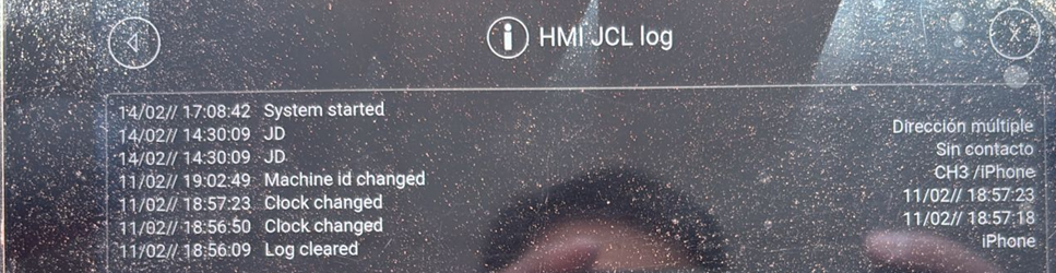
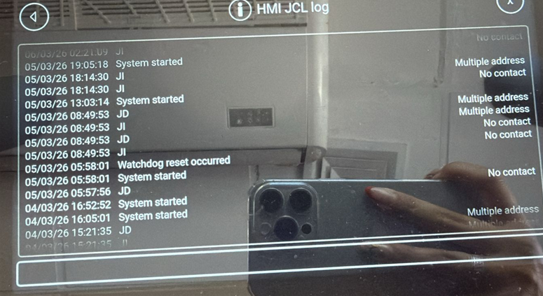
LC5 Multiple Address Error on 2xMD5+MC43
Hi,
We have in a electric cabinet one MC43[0] with a MD5[2], then we have a wired console 30m away with other MD5[1] together with 2 LC5 joysticks.
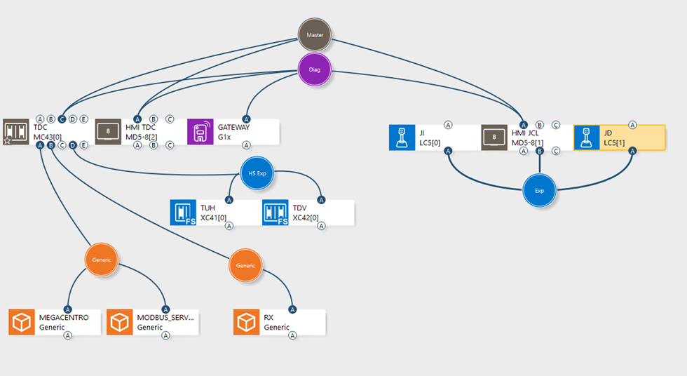
The problem is on MD5[1], we make 3 diferrent connection to check:
1) We first connected the LC5[0]+LC5[1] on its CAN B port as usual in previus system with MD4 we made. But Randomly we gets:
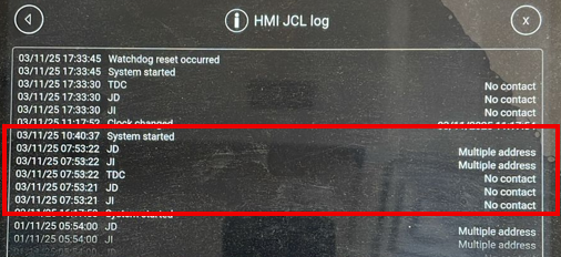
So we double check all the harware and wiring with no problem found. At this point was coneected 0T and 1T on each LC5
2) Then we connect one LC5[0] on the CAN B port, and the other in the LC5[1] CAN C port. Then we gets:
So the problem now is just on LC5[1], but with Multiple Addres Error even being alone in the CAN C port. At this point we added a 120ohm resistor on the MD5[1] to match LC5 termination resistors.
3) Then our last seting was LC5[0] on the CAN B port, and change the address to the other LC5[0] on CAN C port, so we gets:
But in each port, there is only one LC5, so is not posible to have a Multiple Address Error.
The only way to make this work again is reset the whole system. This problem is happen in 4 diferent machines, all with MD5. Other machines with MD4 don´t have any problem.

[1st gen. IQAN] Looking for user maual for IQAN-MG Part no: 5010001
Hi everyone,
I am looking for the original manual/instruction book for the first-generation IQAN-MG module.
I have managed to find the documentation for the IQAN-XP expansion module (Publ. no. HY17-8329/UK) on Parker's servers, but the manual for the IQAN-MG (Document no. 158221) seems to be missing or no longer available for public download.
Does anyone have a PDF copy they could share? I am specifically looking for:
- The full connector pinout (42-pin connector).
- The LED status/error codes for troubleshooting.
I'm working on a legacy system and any help in locating this document would be greatly appreciated.
Thanks in advance!
Customer support service by UserEcho


