
 MC41 not reading specific RPDO from PLC
We have an MC41 connected to a PLC via the CANbus. We push 16 RPDO blocks from the PLC to the MC41. We are on our 10th unit and suddenly on unit #10 we are not getting any values from RPDO 11, and it is greyed out when we look at it with IQANdesign. Help?

Run fault PID 90131 bluescreen crash
Hello,
I am currently working on a machine that uses an IQAN system with an MD4. For some context: it’s a mobile hydraulic machine driven by a diesel engine. I’m running into an issue that I haven’t been able to pinpoint to a specific cause, and I’m wondering if anyone recognizes this error code or has ideas on what I could try next.
The error code I get is:
Run fault PID 90131 TID 14 Signal 11 Code 0
The situation is as follows. When I start the machine, everything initializes fine. The whole IQAN system comes up normally, the UI works, and I can operate the control system without any issues. When I give the signal to start the engine, it works in two steps:
First, the engine ECU is powered up. Then the ECU sends an OK signal back, after which I need to trigger the start again to actually crank the engine.
The ECU and the IQAN system communicate over CAN. However, as soon as I give the first start signal and the ECU powers up, the MD4 immediately goes into a blue screen and completely locks up. Nothing responds anymore, and I can’t recover from the error without completely disconnecting the system and doing a full reset.
As far as I can see, there’s nothing useful written in the logs that I can trace back to the blue screen—only the information shown on the display itself.
I’ve been trying to diagnose this for a while now, but I’m not sure what could be causing the fault in the first place. The only thing I could find online was a post mentioning CAN bus overload, but I don’t really see how that would apply here.
At this point I’m mainly looking for ideas on what could cause this error, or where I should start with further diagnosis. Any ideas are welcome.

Problem using Current CIN sensors
Hi,
I need some help.
I have trouble using CIN sensors.
I have no problem with any others sensor types, but with almost all current sensors (4-20mA), I get an error with the signal (24mA) after some use.
But not all the time.
For exemple, here I have some undesired spikes while measuring.
Spikes are very short so I can't read +24mA in IQAN but I think if there was longer, I would have 24mA, so more than my scaled value at 20mA
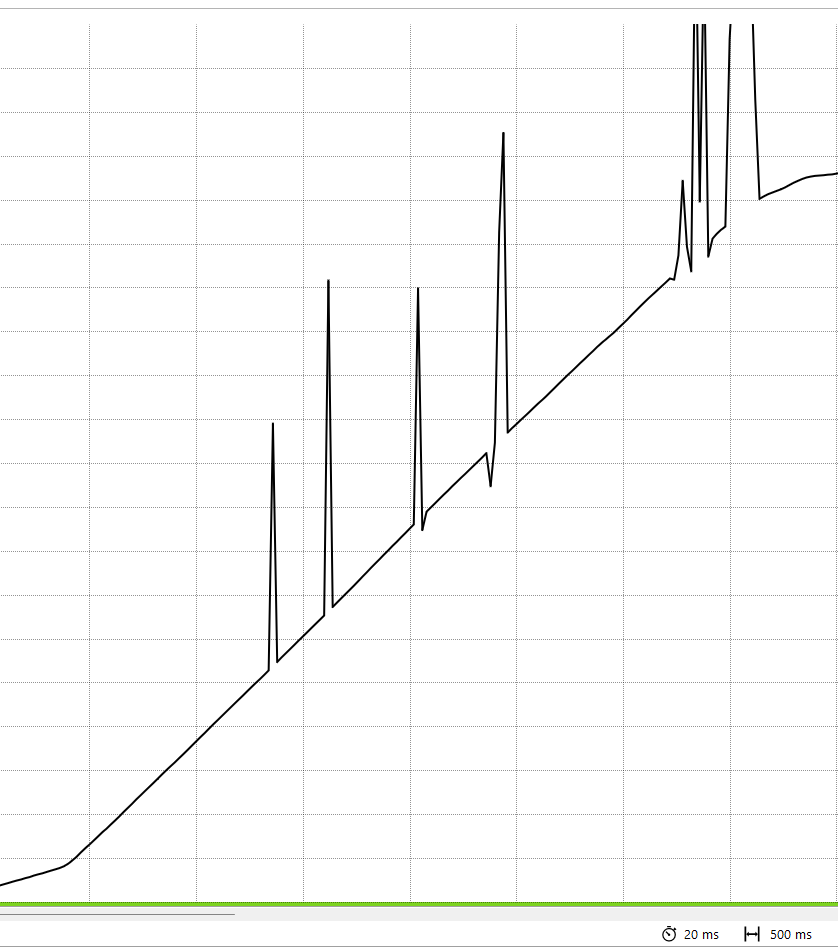
For this exemple, the value come back to a good value quickly, but sometime it stays in error ~= 24mA
Have you ever had similar problem ?
Do you have some advises ?
I can't use Vref+5V because my sensors can be supplyed between 8-32Vdc.
The sensors used are made with 3 wires : +24V / 0V / Signal
So the wire 0V is connected to the 0V of the battery, but on every machine, the 0V of the battery is conencted to the chassis of the machine.
Iin the manual it is recommanded to do not connect the 0V to the chassis. It's not possible on mobile machine.

So we tried to connect the 0V to the VREF- but it's doesn't work obviously.
Is there a way to have a VREF for sensors that supply about 10Vdc ?
Hope someone has some experiences that can help us to understand this problem with current sensors !

MC42FS Error code R4:2 1:1:3 I/O startup test failed
Got the R4:2 1:1:3 I/O startup test failed error on a MC42FS module.
Even when I only put power (24v external power supply) and a address tag on it.
Tried to put an empty program on the controller. The controller is installing the program but when it restarts it keeps coming back with the same error.
Is there anything I can try to fix this?

MC2 Questions
The MC2 unit is now obsolete, but we still have units in the field that we need to support, the MC2 unit went through 2 part numbers in its life time as I can see, 20070899 - replaced in 2015 by 20077787.
What is the difference between these unit and if I found an old one for sale would I still be able to use utilize it?
Can the MC2 unit (20077787) still be purchased by special order if needed?

HS+LS output EMF capability
Would like to use the HS+LS configuration to control the HV contactors in an Hybrid configuration. I am reading note about using Diode to protect against EMF. But I cannot find specification on acceptable EMF level? Our contactors have built-in EMF clamping diode rated at 150V?
Also how does the open circuit detection in an off state works? injecting a current i am assuming. How much? Just want to avoid issue with Dropoff voltage for the coil.

Driving Pulsar with the PWM on MC43
Hi There,
Hope all is well,
Is there any possibility to drive Proportional 24v 33Hz Pulsar valves with the PWM outputs from a MC43 ? Reading the manual it states that this will not work from MC43,but reaching out to see if it is possible.
ATM I am using the proportional flow from the pump and making the Pulsar more like an ON/OFF, This is working currently but would like to use the Pulsar proportionally.
Thank you

Max bus length
What's the realistic max bus length of master and diagnostics? I have an application that requires 2 masters at approx 100m apart from one another. Can these have master and diagnostic bus at this length?
I recall seeing in the IQAN instruction manual 40m is the recommended but maximum is 100m. Is this length take into account the 40 twists per meter, as 40 twists per meter at 100m length between modules would mean cabling of in excess of 100m actual cable length? If IQAN bus works at 250kbs, does this follow standard bus protocols and have a theoretical max of 250m @ 250kbs?
Will the soon to be added HS busses help any limitation?
I can always add an additional node to act as a midpoint transferring the data from one bus to another, effectively reducing the max length of a master bus to 50m, however it would need a diagnostics bus shared between all the master modules, which would be the maximum distance of 100m, and therefore the limitation?
Would CAN routing help me here with a central node that just runs its own independent program and routes the diagnostic bus and master bus through, and therefore has its own application file separate from the main 2 node application file?

MC4x/XC4x 12V 30W solenoid overload error
What is the suggested solution for driving NG6 valves with standard 30W solenoids at 12V system voltage with MC4x/XC4x modules?
We use the HS+LS digital outputs for driving Parker D1VW valves with "K" code solenoids in a 12V system. As stated in the instrucion book, max load per output is 2.5A, but the measured current is 2.7A (as in the D1VW catalogue). The measured solenoid resistance is 5 Ohm, but it should be within 7-14 Ohm (MC4x/XC4x instrucion book).
30W solenoids are standard at other valve suppliers too, so changing the valve isn't an option. Change the system voltage to 24V also isn't possible for this project.

MC2 constant red status LED
Hello,
got a constant red LED on the status light from a MC2 and "no contact" and IQAN MD3 screen
that constant light is not explain in the book, i would guess an internal crash, could you confirm?
Is MC2 module replacable by MC2-M14 ? any software update needed ?
Thanks in advance
Customer support service by UserEcho


