
 Lifetime of MC43FS
We have a project that is to be used for the next 40 years. It is a functional safety system that utilises MC43FS. These modules will likely be superseded multiple times (probably due to enhancements in electronics etc) after the 20 years lifetime shown in the manual:
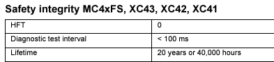
To guarantee functional safety, presumably its recommended we remove and replace the MC43FS after 20 years as described in the manual regardless if the module is working correctly? I'm trying to avoid re-assessing the system in 20 years time and fitting a safety controller available in 2045. Therefore I intend on having a brand new MC43FS available for when the system needs a replacement module in 2045.
Is the 20 years triggered as soon as the module is powered up, therefore we would need to clone the software only when we want to replace the module in 2045 (rather than installing software now and starting the 20 years timer)? Or has the module 20 years been triggered from manufacturing date on the serial number?

Does any of you know why md3 keeps going over a pre-set angle causing system to dead head?
I already lowered angle and still goes over preset angle. What other setting can cause it to go over.

MC2 controller relay protection. Failed MELF resistor DOUT
I have 2 different units both using MC2 DOUT to control a large solenoid. Both have flyback diodes installed correctly near the relay. After several years of use, both have the MELF resistor for that DOUT failed inside the module. How can i prevent this from happening to a new or repaired module? Fire a smaller relay to control the large solenoid? Add a capacitor to the DOUT line? Another diode inline on the DOUT line?

Looking for a IQAN mdl2 with sim card slot
Any of these still out there?, we're looking for one for a log harvestor. Also wondering if just the circuit board can be purchased.

How to Perform Short to Ground and Short to Battery Tests on Parker ECU (like MC43FS)?
Hello,
I am working with a Parker ECU (MC43FS), and I need to test for short to ground and short to battery faults on specific pins. Could you please provide detailed instructions or best practices for performing these tests safely? Specifically, I am interested in:
- How to safely simulate a short to ground on the pin and verify the system's response.
- How to simulate a short to battery and what actions I should take to test the system's reaction.
- Any recommendations for multimeter settings or test equipment to use during these tests.
- Expected behaviors or diagnostic codes (e.g., LED blink codes or error logs) that the ECU will produce during these failure scenarios.
- Any precautions or potential risks I should be aware of during testing.
Thank you for your assistance!
Best regards,
Sayan Biswas

Programming an MD5
I received my first MD5 and am trying to flash it on the bench. There is no Ethernet hookup so I'm using a G12. It is taking forever and I'm only getting a couple percent done before the MD5 goes blank (after around 10 mins) and seemingly stops. My questions are, what is the fastest connection to flash a system with the MD5? If its CANbus, what is the hardware/ how do I wire it into the system. If its Ethernet, how do I wire that into the system. I have also tried to create a program utilizing an MD4 and MD5 to utilize the Ethernet and the program wont recognize the MD5. I heard the G12s are fast but there is no way it will work as the main programming connection considering the experience Ive had with them.
Safety COUTs as DOUTs
We have a project that requires control of multiple cylinders, each cylinder is connected to a double acting valve, 2 separate coils, one for each cylinder movement (in/out). These outputs must be safety in our application.
Reading the instruction manual for the DOUTs on MC43FS, it states we must use only one DOUT HS and one DOUT LS per output when its being used in a safety application, so the controller can switch the valve off by either side in event of a fault. Therefore I have concluded we can only have 5 DOUT safety per MC43FS. Or in other words, 2.5 cylinder valve controls.
Can I instead use COUT, and therefore each cylinder function can be driven by a complete COUT A? For example, i can technically connect 10 cylinders, in/out, i.e. 20 valves? I would have to ensure the current does not exceed the limitations of the groups, but does having the shared COUT + affect the safety aspect of a COUT? There is a note saying all COUTs are safety, and nothing about sharing pins like there is under DOUT so I guess I can overcome my issue of limited DOUTs for safety?
I guess if there was a function other than driving a component in a direction it would not be possible, as you can only drive a COUT in either + or - direction, i.e. not both if you has different valves to energise, which could be at the same time.
Also it explicitly states no diodes on a coil connected to COUT (I guess for regulation), does this still apply if I'm using COUTs digitally, ramping from 0-100% and 100-0%? Would the collapsing digital coil cause damage to the COUT driver?

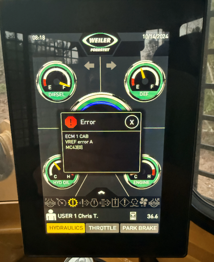
What causes error code VREF error A on MC43?

Looking for MD4
Hi, I'm looking to purchase a second-hand MD4 (and XC42) to replace our current control system. Has anyone got these in stock that could be shipped fairly quickly?
Thanks in advance!
How does an open load error effect the operation of a PWM HS+LS output.
I am testing logic with a MC43 and using a PWM HS+LS output.
In the system we are using both sides of the output (+ and -) to drive two individual devices.
Both should never operate at the same time.
To simulate one of the device not operating, we unplug one of the solenoids.
With logic, this automatically causes the other side of the output to now function.
Basically, if the + side fails, it should switch to the - side and operate.
We are getting an open load error on the output with one of the solenoids unplugged and it does not allow us to operate the other solenoid on the PWM HS+LS output.
Is the output designed to shut off both sides if one side detects open load or should the other side work if one side detects open load?
As an example:
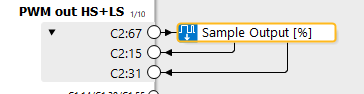
If the solenoid between C2:67 and C2:15 is unplugged, but the solenoid between C2:67 and C2:31 is plugged in and fully operational, should we be able to command it with an input signal of -100?
Customer support service by UserEcho


