
 MD5 Power capability
How current can I draw out pins 56 (bat+) and 29 (bat-) if I am using pins 42(bat+) and 43 (bat-) for the input power. I need to power 2 each IQAN sv120 cameras.

What material is used for the molded rear panel of the MD4-10?
What material is used for the molded rear panel of the MD4-10? I was asked by a customer and couldn't find anything about it in the catalog.

24V MD4 with 12V relay on LS DOUT
Can a 12V relay be driven by the LS DOUT of an MD4 supplied with 24V without protection or diagnostic issues?

l have an MC2 and want to replace ,what is the closest replacement

Actuating 24Vdc coil with MD4
Trying to actuate a 24Vdc coil for a skinner valve with the MD4. I know the MD4 only has LS digital outputs so I am wondering if we would need to use incorporate a voltage divider? I plan on using a relay for that coil as well.

Green line appeared on MD4
We have installed a brand new display in a battery powered rig this week. Its serial number starting with 2305 and production date of 230202.
It has been OK for a week but after the battery in the rig went flat, this line appeared:
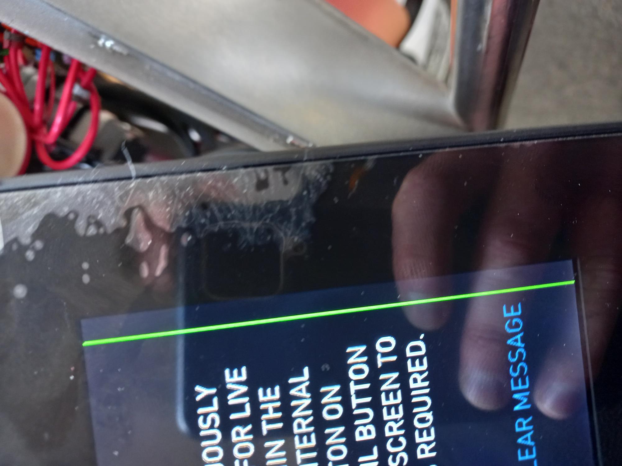
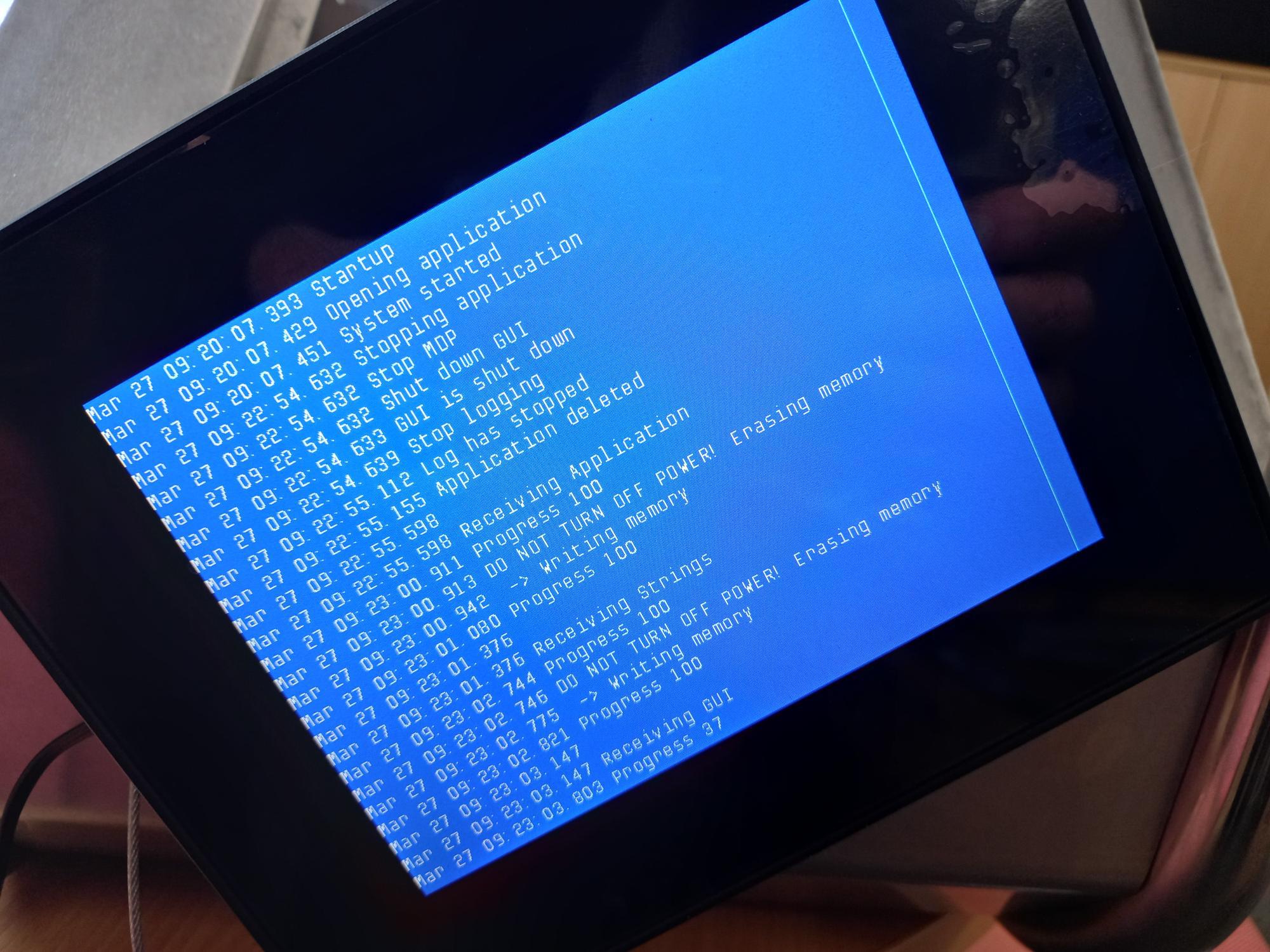
Only thing I can think of was the battery was depleted and resulted in the display flashing when the battery got to a level where it was unable to power the module. It performed OK after the battery was recharged but after a few hours the line appeared.
Anyone had this problem or similar before?

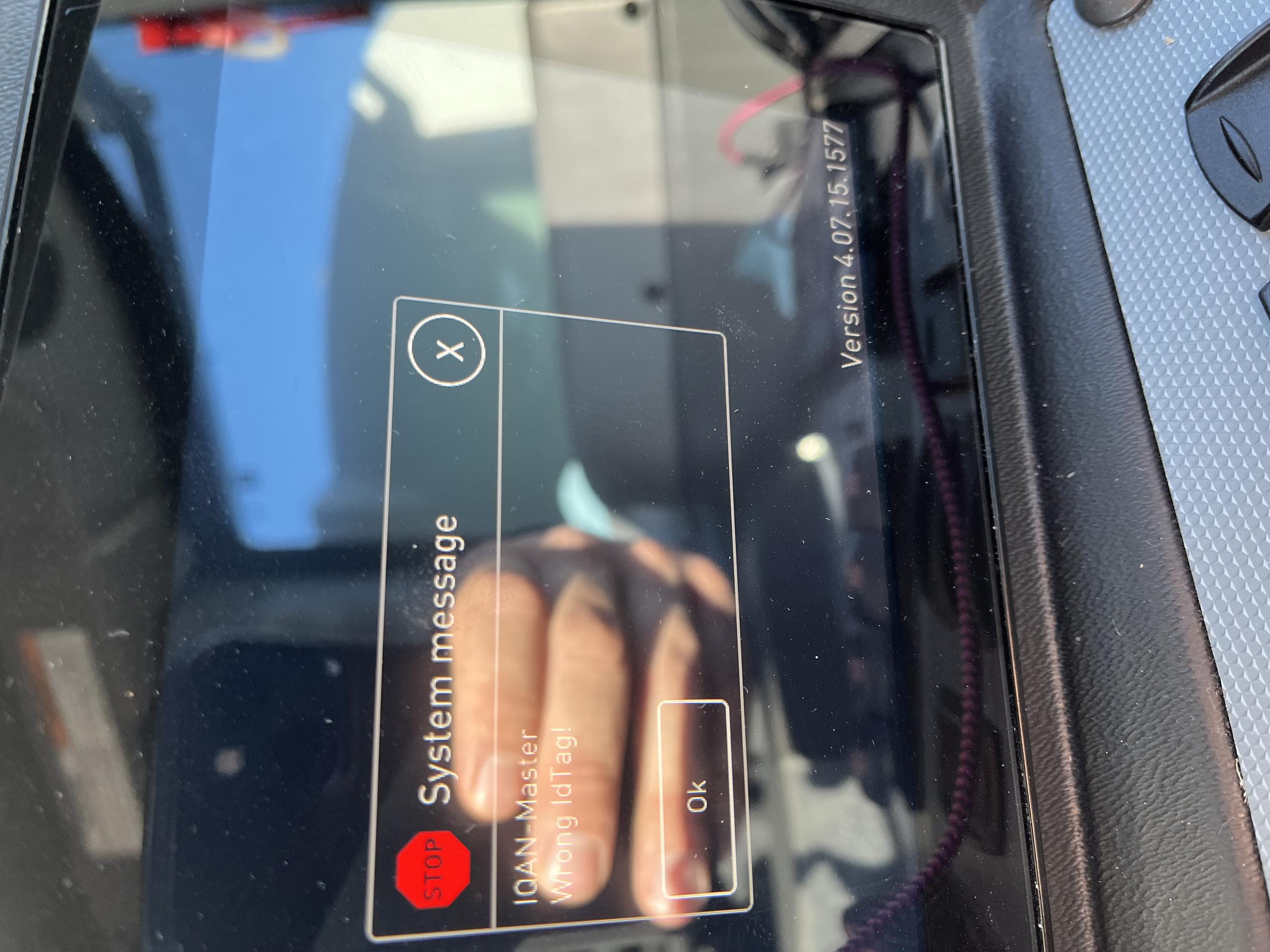
Wrong ID Tag on MD4 Start up
When powering on the MD4 the system message "IQAN-Master Wrong Id Tag!" appears on the screen. This does not happen every time the machine is powered on but is getting more frequent. Restarting or shutting off the power to the MD4 does not resolve the problem consistently. The screen remains black when this issue happens. Any help is greatly appreciated.

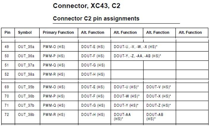
OUT pins a/b
Apologize that I have to use the wired topic. Otherwise the submit window will go to search result and not be able to submit my question.
Why there are OUT_xxa and OUT_xxb? Are there any relationship between them? Have to use them in pairs?

CAN bus critical error
I have issue regarding CAN bus critical error on the MD4,
can any one suggest me to reification above issue.
I am waiting for your valuable reply.

Open Load status not resetting in all situations
I am having a problem with the open load detection on a COUT on am MC43FS
- I am running IQANdesign 5.03.14.5040
- The manual indicates that the output detects open load two different ways which may be true, but the controller responds in three different ways.
- When the output is off, if the load is disconnected, the controller will set the open load status to TRUE, when the load is reconnected, the controller will set the open load status to FALSE and allow normal operation.
- When the output is on and passing some normal current, if the load is disconnected the controller will set the open load status to TRUE and turn off the output, if the load is reconnected, the open load status remains FALSE, and the output remains off until the command is set to zero. Setting the command to zero causes the controller to reset the open load status to FALSE, after which the output will respond to a normal current command.
- When the output is on, AND some fault causes the resistance of the load to increase such that less than 50% of the commanded current can be pushed through the load, the controller will, set the open load status to TRUE and turn off the output. Unfortunately commanding the output to zero does not cause the controller to reset the open load status to FALSE. This acts like the open load status is latched to TRUE if it was tripped by “extreme saturation”
- It is my belief the third response is a bug in MC43FS because, a MC2 running IQANdesign 4.07.7.4605 works as expected I.E. commanding the current to zero would reset the open load status to FALSE Such that the controller could lower the current and try again.
Customer support service by UserEcho


