
 Frequency input MC4xx
Hi,
We have installed a speed sensor (PNP, 15000Hz) onto a MC42 frequency input (pin C1:28, PD).
The problem we have is that the raw value only goes up to about 2800Hz then zero's out with no further reading and we need to get a reading up to at least 5500Hz.
I have configured the input settings to: Max HZ -> 15000 and also the Scaled Maxed-> 15000 to mach the sensor's capabilities and then use the raw reading to scale a RPM value.
We tried adjusting the sensor closer to the ring gear, but no improvement.
So I did a test to see if it might be the sensor that is faulty by connecting the sensor to a different type/brand of controller. It immediately worked and gave the correct reading constantly.
The question is now... What am I doing wrong on the IQAN side?

Tsc1 Throttle Control interface
ISO a simple Tsc1 interface module that can convert basic analog throttle Inc/Dec input, to Tsc1 messaging output. Don't really need/want a display if its possible to do with out one. Please bare with me as i'm not very familiar with whats possible and whats not. Thanks Josh

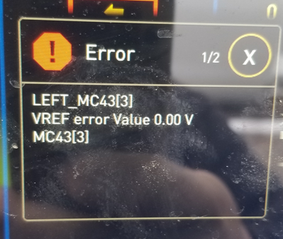
MC43 VREF error Value 0.00 V
What can be the cause of this error ?

XS2 Dout to +bat?
I'd like to have IQAN control be paralleled with switch control. This specific application will be a drop axle. I want the IQAN to drop the axle in certain situations, and have a switch that will drop it at any time, even if the control system is powered down,
I believe I have to protect the module from back-feeding, correct? Will just diode protection be enough or do I need to have the Dout controlling a relay that would toggle the input between the switch and a +bat source?

diodes on coils
Hi there!
we are using prop valves for an application. and we use a cout (current out) to control them. but over the 2 pins of the coil there is a LED with a resistor. and in the instruction of our module (MC43) they say: Do not instal diodes over the coils.
so i was wondering: is a LED a Diode in this application? Do i need to remove the LED?
Thanks for helping!

IQAN-DG
I have an old faulty IQAN-DG here for repair.
Can someone please send me a diagram of the rear CI, CAN1 and CAN2 connector pinouts.
Thank you

MC43 Error Code
I have a MC43 with the following blink code 4 red, 2 yellow, 1 yellow, 1 yellow, 1 yellow. What do the 3 yellow blinks at the end mean? This happens intermittently when the module first gets power.

If it's occurring on start up, the likely causes are battery voltage exists on an output before the module powers up or a slow rise in power supply voltage. Possible causes are covered in appendix B of the instruction book.

PWM Input with frequency >500Hz
I am considering using an MC41 with PWM signals as inputs. These signals come from joystick thumbwheels on excavators made by a large multi-national OEM. My problem is the spec on the frequency of the PWM signal from the thumbwheel is 500Hz +/- 50Hz. I see the max allowable frequency from the MC4x catalog is 500Hz. Wondering if the MC41 will work with 550Hz PWM frequency input.

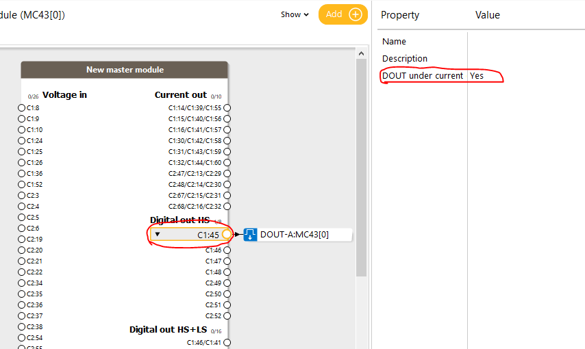
MC41FS Digital out HS disabling under current shut OFF
How this can be done? Did not find from channel properties.
You find the property on the pin in the module view.
MC41 restart after low supply voltage event
I am using MC41FS in non safety application. During cranking voltage drops, but not low enough to reset module.
Module hangs up and stays that way until power recycle. Can I restart application back up with SW?
Customer support service by UserEcho


