 MD4 functionality after screen crack
Say the MD4 screen is broken or cracked, would the I/O and CAN messages still work on the module, assuming no damage to the board in the enclosure?

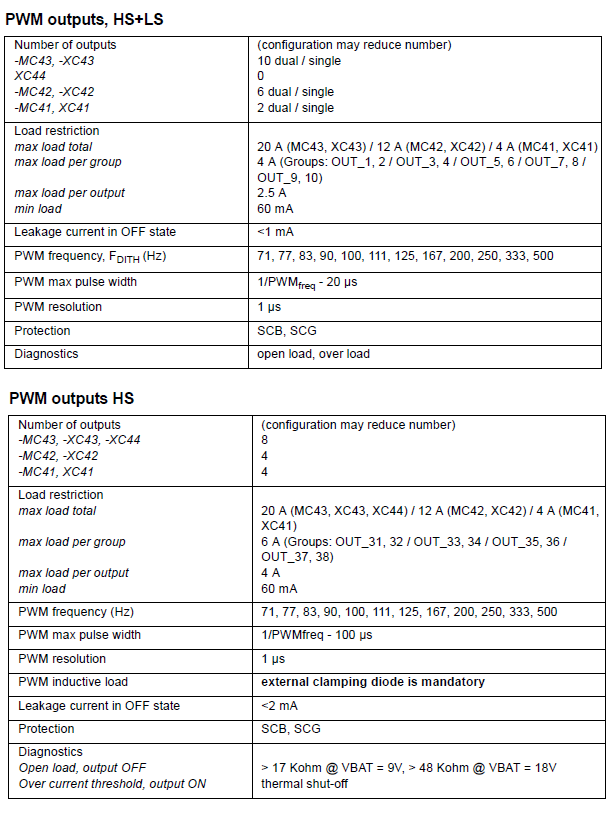
 MC43 PWM out
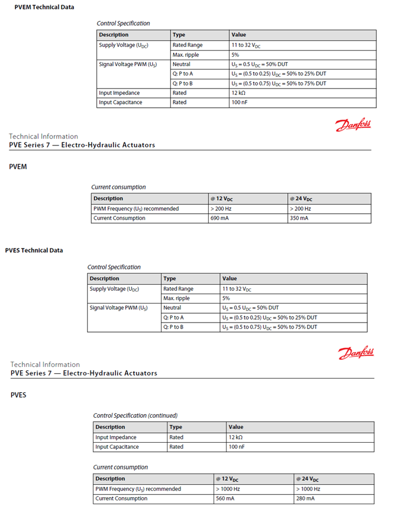
I am working on the control system using MC43. Please let me know urgently whether I can use MC43 ‘PWM out HS+LS’ or ‘PWM out HS’ to control Danfoss PVES or PWEM proportional solenoids
From MC43 instruction book:

From Danfoss solenoid specifications

Kind regards,
Richard Kowalczyk MIEAust CPEng RPEQ
RKad Engineering
32 Kingussie Ave
Castle Hill NSW 2154
Australia
☎: +61 2 98940750
📲 :+61 431 639 295

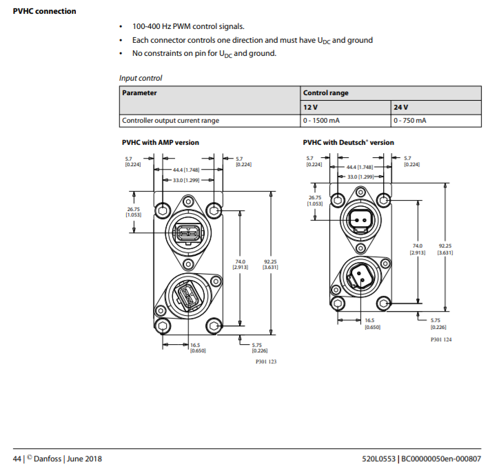
Generally driving Danfoss PVG valves with IQAN Control system, we advice using the PVHC control option from Danfoss. You can drive the PVHC direct from the IQAN COUT current control output, Simple and works well.
Ratiometric input signal requred by PVEM series cannot be controlled by IQAN available Outputs, same for PVEP PWM signal controlled modules as they have high input impedance (5 kOhm), requiring extra Pull-down resistors to connect to IQAN PWM output
Another, more expensive, option is using Danfoss CAN control module PVED series, then need to include CAN protocol in your IQAN application


 Voltage input to MC2 from an amplifier
Hello Team,
I've been working with potentiometers and parker sensors (pressure and temperature) before without any problems, but now i need to use a voltage output (0-5V) from an amplifier as a voltage input on my MC2. The amplifier is connected to a sensor and have a standard +- output. I've tried to connect + to one of the VIN-x and neg to -VREF (or to the common terminal on the power supply). Tried different combinations but the measurement mode on the MC2 shows zero input all the time. Multimeter measurements confirm that the amplifier output around 1V. Logically don't see why it should now work, but maybe you can advise how 3rd party sensors (amplifiers) are connected to parker systems? Thank you!

 Startup Multi-Master
If an application have a MD4 and MC4X and they are connected as multi-master. How does the startup looks like? Will the MC4X start communicate with peripherals as soon its booted or does it wait until MD4 is booted?

 CM0504 Current Limit
Regarding th CM0504 module. What is the time to trip for the 25A current limit? If a motor is powered and spikes above 25A, will cause the module to fault? And will it recover?

 XA2 no connect four red LED blinks
I have an MD3 running a small program and an XA2 expansion module. When connecting only power , GND , Can-H, Can-L and ID tag #3 to the expansion module I get a four red LED blink with no Orange/ Yellow.
No connection message on the MD3.
The ID code in Iqan Deisgn is the same as ID tag.

Hi Anthony,
I am glad it was just a case mistaken identity and the XA2 module was in fact an XT2 module !

 Conneting IQAN MC41 to PC
I need to know what are the possibilities to connect MC41 controller with PC to flash program into controller and for diagnostics.

You can only connect via CAN to a MC41.
So you need to have a USB to CAN interface.
https://forum.iqan.se/knowledge-bases/2/articles/231-usb-to-can-interfaces

 MD4 +RTC RESISTOR
The MD4 documentation states to use 1.5K ohm resistor on the +RTC circuit. Is the 1.5K ohm the only type that is usable, or is there a range that will work?

 MC43 Fusing
The MC43 documentation states to use a single 40A external fuse to protect the module. Is it sufficient to run two single 20A fuses, one on each +BAT connection?

 XC-23 minimum input voltage
Hello,
I have an H-Bridge that drives a DC brushed motor on 12V. I need to determine the PWM ratio being supplied to this motor by the H-Bridge. There is no other signal that could get me this information so I am contemplating hooking both sides of this motor to PWM inputs on the XC-23. Before doing such a thing, I looked at the signal using an oscilloscope. Basically, the signal is 0-12V most of the time but dips below 0V when the ON time finishes. The lowest voltage read with the scope is -11V for a short period of time.
There are no Absolute Requirements for negative voltages on inputs in the datasheet of the XC-23. What is the absolute minimum voltage that can be applied to a PWM input of the XC-23 without damaging it ?
Guillaume
Customer support service by UserEcho


