 Externally Mounted Module, Diodes?
Hello,
We are going to be mounting an XC43 externally. The module and connector are rated for it, IP6K9K.
Has anyone else done this?
How does one go about neatly mounting external diodes for the digital outputs?
I need diodes that go between HS DOUTs to ground and between the pins of HS+LS DOUTS.
Regards,

 Incandescent lamp on XC23
Hello,
I am using a DOUT LS on XC23 to drive a 12V incandescent bulb on an instrument panel. In steady state, the lamp draws 85 mA. I am getting an overload on this output when I try to activate the lamp. I was able to temporarely solve the problem by using a 22 ohms in series with the load. So I believe the problem is the inrush current of the lamp. The instruction book of the XC23 clearly states that the LS DOUT "are designed to drive small loads, e.g. lamps and buzzers". The example even shows a lamp being driven by a LS DOUT.
Can you explain if I'm doing something wrong. If not, is there any fix available to solve this issue ?
Thanks,
Guillaume

 Relay on XC43 HSDOUT caused Open Load error
We've used the 24V DC relay (datasheet is attached) on a XC43 High Side DOUT, but it doesn't seem to like the relay and show us a Open Load error. Could you please help us understand why this happened? Is there anything we need to pay attention to when using relay?Section-1_35_2018.pdf

XC43 multiple DOUT overloads
We are having a problem with XC43 giving overload errors in multiple DOUT's at the same time.
Construction of the application is MD4 + 2xMC43 + 3xXC43, running with IQANdesign 6.08.
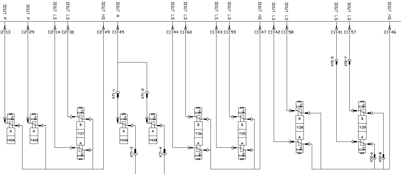
Problem is only in one of those XC43's. We use those DOUT's to control two different kind of solenoids, connected as shown below:

Fault codes are occurring only in:
- C2:29 (load 0,83 A), C2:13 (0,83 A), C2:30 (1,29 A) and C2:14 (1,29 A) overload simultaneously
- If you activate only one of these DOUT LS's, every one of those are giving fault code
- C1:58 (1,29 A) and C1:42 (1,29 A) overload simultaneously
- If you activate only one of these DOUT LS's, both of those are giving fault code
- C1:60 (1,29 A) and C1:44 (1,29 A) overload simultaneously
- If you activate only one of these DOUT LS's, both of those are giving fault code
Sometimes you can drive a day without having any fault codes, sometimes fault codes appear at the first activation at the morning. Even when the machine is standing still, only ignition on and you are activating those solenoids, it can be that you can activate those 50 times without problem and then suddenly the next activation gives you the fault codes.
We have replaced that XC43 with the other one installed in the same machine, still giving the fault codes. The original XC43 didn't give any fault codes when installed to another location. We have checked and measured all the wires, not shorted to the ground or to each others. Measured the coils, everyone has the correct resistance. Replaced all the diodes at the solenoids' connectors, no change. We have dozens of machines with exactly same construction and none of those are having the similar problem.
Any ideas how we should proceed with the troubleshooting? Thanks!

 Max current on XC43 -VREF pins
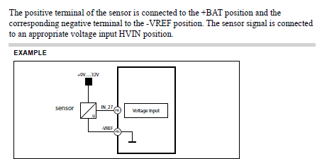
We are providing some sensors with a 0V supply through the VREF circuit on XC43 module but cannot find the maximum current capacity of these pins. The manual states VREF has a limit of 150mA, but is this limitation on both the +ve side and -ve side?
I was under the impression -VREF is connected internally to the -BATT terminals, therefore does this mean there is a higher current limit? I cant find a value in the manual:


 XC43 Output High
we have strange behavior which XC43 Has constant high output as soon as get powered on ,
we have replaced 3 modules but the same situation was income .
temporarily that output sealed and waiting for your advise .

 XC44 address tag error / no contact
Hi Gustav,
We are experiencing issues with XC44 reporting no contact error and ID tag LED error.
Test bench system consists of the following:
- MD4-10 (6.08.24.8051):
- Adress tag 1
- Can bus A – terminated
- Can bus B – not used
- Can bus C – not used
- Can bus D – not used
- XC44 module:
- Address tag 2 (pin 4 and 20)
- Can bus A – terminated
- XC44 original harness on C1 and C2
- No inputs, no outputs for testing purposes.
- Tried different, known address tags
- C1 pins have been verified.
Pushing the project to the MD4 has not fix the problem. We tried the same setup with IQAN 7 – same results.
Our field service started reporting same issues in the field where the XC44 is reporting no address tag errors.

 Terminated or not address tag
Hello,
Where can I read about when to use terminated address tag or not? E.g. 0T and 0 tag? When prototyping discrete resistors may be useful but will it work with just a resistor of correct value? Please advise.

 VIN voltage drops
Hello,
I have an odd issue, maybe power or ground reference related.
XC43 IQAN 6.08, sensors powered using the main 24VDC not regulated VREF.
When I start driving valves with the module the reported voltage from my VIN sensors drops by up to 5%.
It happens to all of them irrespective of the sensor type.
It also jumps around a ton.
This makes a huge difference on my 0-5800 0.5-4.5V sensors.
200+ PSI, not good for sensor accuracy.
Any ideas of what to try to fix?
Regards,

 XC43 INPUT ERROR
I am working with a couple customers who are having "No Contact" Issues with XC43s installed to replace XA2s.
When looking at the XC43 module itself, the error code is 1:2 (one red, 2 yellows).
I'm assuming the module is getting an errant input somewhere which is causing it to shut itself down.
I would like to better understand this error code better. What causes an input error and under what circumstances does it cause the module to stop communicating with the master.
Customer support service by UserEcho


