
 XC44 HS+LS Overcurrent Update
I am still unable to reply to previous posts with the same error being reported as before when I attempt..
In reply to Gustav's comment on this post: XC44 HS+LS Overcurrent Follow Up / Hardware / IQAN
"Ok, the disabling of the function group explain at least a part of the behavior you see.
When disabling the FG, the DOUT deactivate. Diagnostics is still running, so when disabled all checks for output off are running. In IQANdesign you will only see channel status disabled though.
At what events do you disable? Only before cutting the highside externaly?
Or also during normal deactivation of the output?"
The function group is only disabled on Estop. Before an estop event the output functioned as normal, the estop being triggered starts the overcurrent issue.
Original post: XC44 HS+LS Overcurrent / Hardware / IQAN
XC43 COUT Open Load Threshold
What is the XC43 COUT open load threshold when the COUT is off?

DOUT error code flash on XC23 when output is disabled in IQANdesign
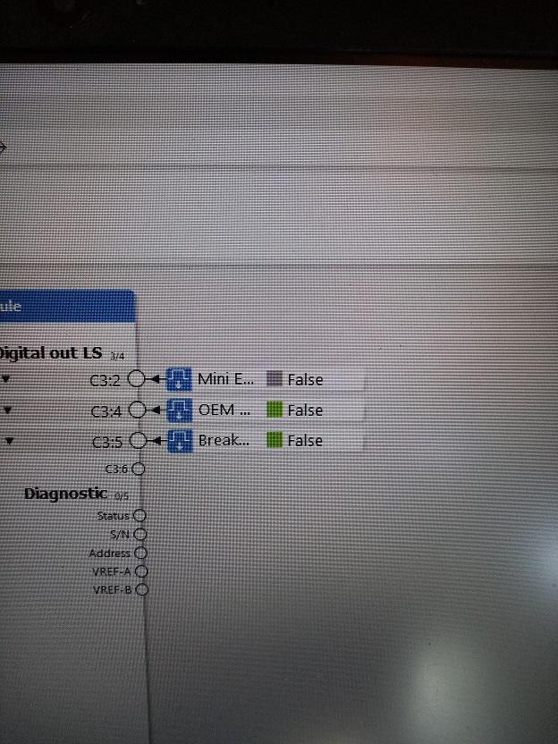
We have an application which has an optional function group containing a DOUT on an XC23 module. This function group is enabled or disabled using a digital parameter. With the function group disabled we get the output grey and 'disabled' state when measuring with IQAN Design, which is correct:
We also have no errors on screen stating open load (we have nothing connected to output because this machine has not got the optional extra fitted). XC23 module has error code flash of DOUT, I suspect open load. Its not logging any errors or open loads in any logs within master module, viewing state of the module using IQAN Run I also get 'OK' and no errors on status screen just the LED status is showing incorrect state directly on the module:
https://www.dropbox.com/s/gt9sga2eys10gg4/VID_20210720_101414.3gp?dl=0
If I delete the output from IQAN Design the error flash on the module disappears and it goes a steady amber flash, no errors.
Has this been fixed in a newer version? IQAN Design 5.06, MD4-5 M19 and XC23.

XC10 DOUT(LS)
Hi everyone,
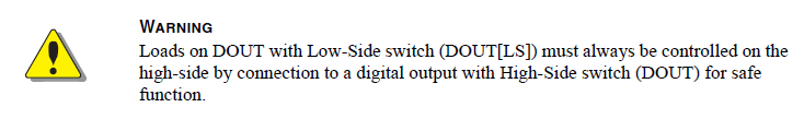
I have been working on a quite complex system. When using XC10 all relay coils (or valve solenoids) controlled by DOUT(LS) have been powered from +BAT and it has been working fine. However checking program, for no reason, have found in the the Instruction book that one or more DOUT should be used to power these coils or solenoids. Is there any risk with what I am doing ? I have checked that for MC43 and MD4, that I have been using on the same system, it is allowed to use +BAT for power. I can of course do it by book but the program would become a little bit awkward and messy.
Any comments will be much appreciated
Richard Kowalczyk
RKad Engineering
Australia
In the XC10 instruction book

XA2 VREF Failure Effects
This is a two part question regarding the criticality of VREFs for IQAN Modules. We use an MD4 and XA2 in our system. On the XA2, we use VREF to support a three axis joystick and one pressure transducer (4 VINs).
We received a report from the field that a short circuit between VREF and ground caused the XA2 module to fail completely resulting in "I/O No Contact" IQAN Error Message on the MD4.
Is this a typical or expected failure mode for an XA2 with a damaged 5V reference voltage regulator? Or is it more likely there was a mis-diagnosis from the field? I can't think of a way to validate this without destroying an otherwise healthy XA2.
Would this also be the case in an MC42?

XC43 PWM Output voltage jumping from 6V to battery voltage randomly
I'm having an issue where the PWM outputs jump in voltage to battery voltage seemingly randomly and with no change in the displayed output on IQAN run. Anyone know what is going on?

XC42 Analog Input Pin#8 Internal Short?
We had a XC42 where we use a hall effect analog device that was mapped to pin 8 and configured as an analog input. The device was connected to Vref A so uses a supply voltage of +5v and provides 0.5-4.5v thru 180 deg of rotation. We first started to see it only indicating from 2.5-4.5v and then eventually we got fixed values that fluctuated based on if the hall effect magnet was present or not. After some trouble shooting we removed the wire from pin at a connector and were getting a fixed voltage of around 4v at pin 8. With this removed the magnet rotated gave us 0.5-4.5v at the output of the sensor.
A data sheet of the sensor is attached. Model # is RTP180LVNAA
We ended up remapping the input to pin 52 and it all worked fine again.
It almost seems like the pull up resistor in the channel was "turned on"???Honeywell RTP Sensor

Outputs Missing in IQANDesign
I've noticed that the following XC43 pins appear inaccessible via IQANdesign:
C1:61
C1:62
C1:63
C1:64
C2:69
C2:70
C2:71
C2:72
Is this by design or am I missing something? They're listed as PWMOUTs or High Side DOUTs in the manual.
IQANdesign 6.04.5.5888
I have not checked the other XC4x modules.

VREF error on XC43 Enable
Working on a project in which 2 XC43 modules are not supplied with power until the MD4 commands a safety relay contactor closed.
I've worked through almost all the bugs, but I'm getting a VREF A error as soon as the XC43 modules enable. I've tried leaving up to a 30 second delay after powering the XC43 modules to enable them, but the error still pops up for one cycle and then shows up on screen (Watching in a measure group, VREF starts at 0V for one or so cycles, then goes right to 5V). All the sensors read fine, just have the error at system start.
Is there any way to delay how long it takes for the VREF error to show

W out engine alternator connect to frequency in terminal C1:24 XA2
Hi to all
Is it possible to connect the terminal W of the engine alternator to terminal C1:24 "Frequency In" of the XA2?
The diesel engine work at 24V , it is an old engine and don't has the J1939 bus.
Customer support service by UserEcho


