
 Connector packed with di-electric grease
Got this photo from a colleague who works in after-sales, an MC41 connector packed with di-electric grease.
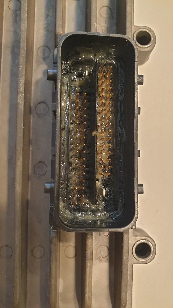
The Molex MX123 is a sealed connector when properly assembled, so adding di-electric grease does nothing to improve protection against water and dust. Instead, it can only cause problems by getting in the way for the pins and prevent contact.
I do not know how widespread this problem is.
Do you guys also have problems with people putting grease inside the connectors?

What's the max current on pin 23 and 35 MC41 FS
What is the max currant on the -V-ref on pin 23 and 35

Display Iqan MDM
Witam, mam problem z programowaniem wyświetlacza Iqan MDM, czy mogę zaprogramować lub odczytać program dla danego urządzenia za pomocą serwisowego, pobrałem program do tych wyświetlaczy MDM, czy muszę wykupić licencję na korzystanie z niego czy jest on darmowy
moze by mi ktos pomogc bo mam wyświetlacze i chciałbym je zaprogramowac bez rozcieńczania pamięci na inne urządzenia
Wyświetlacze nie są już dostępne i wystąpił problem ze starszymi urządzeniami
Dziękuję bardzo za pomoc

Serial info
What does the serial number mean on an MD4 and MC41?
I think it starts with production year and weeknumber, but what do the following numbers mean?
MC41FS Critical Errors
Hi there,
I have a critical problem with MC41-FS stand alone controllers (ie it’s not connected on Multi-Master system). FW level 6.05.18.6047
We see operation continuous for about 2 months with no error, then multiple devices on the same mahcine just stop working ll within minutes of each other (with no CAN output) and no reported/broadcast faults or recorded System Log errors. This problem is seen on multiple machines now, and a pattern is emerging of this failure. Resetting 24V power, resets the module and the error.
Clearly having a module just stop operating with no reported or logged system errors is very dangerous, as we have no means to quickly diagnose.
We have managed to collect the LED blink code when in error state: This sequence is not listed in the manuals.
Blink code
4x RED
Stop
1x AMBER
Stop
21 AMBER
Stop
2x AMBER
Stop
1x AMBER
Stop
2x AMBER
Notes:
- There are 3x MC41-FS modules per machine (all independent)
- MC41FS power supply is continuous 24V
- The machine has a "main" Multi Master system which comprises of 2x MD4-7 and 3x MC43FS modules all on MM system.
- The 3 independent MC41FS modules are connected to each MC43FS module on J1939. As far as MM system is concerned, the MC41's are another J1939 module on the common J1939 line.
- The machine MM system is operated with switched power supply (24V)
Originally I thought this was possibly a CAN bus issue, but no other IQAN modules are reporting CAN bus errors (ie the MC43 modules) as they share the same J1939.
There is one possible interaction between MC43 and MC41 module that could be contributing (depending on what the fault LED codes are from above). The MC41FS module has enabled TDA for time sync, and the MC43 is configured to send TDA PGN onto the shared J1939 continuously every 10 seconds to time sync the MC41FS. As mentioned above, the MC43 modules are connected on switched power, and the MC41 on continuous. So very night the MC43 (and full MM system) is powered down overnight). I am unsure if this is a problem, or has no effect.
Please can someone contact me to discuss this directly. I am not able to share the project file publically.
Julian

Is -Vref and Batt- common on the MC43 module


PWM for controlling fan and coolant pump speed / schematic PWM signals
Hello everybody,
I'm working on a project, where i want to control the speed of a brushless SPAL fan and a BOSCH cooling pump via a PWM-Signal from a PARKER MC43.
However, I'm running into some issues with this.
1- First of all, I dont know how to wire the components. The fan und the pump, both have only 3 pins when it comes to PWM controlling. 24V + , 24V ground and the Sinal pin for PWM. On the MC43 i do have 2 pins per PWM signal. Could anybody show me how to wire those components? I added a unfinished schematic:
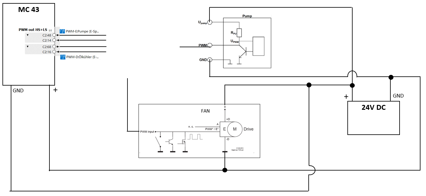
Maybe I'm missing something completly obvisous here but additions to not knowing how to wire these components, I don't understand what has to come on the PWM*/E* pin of the fan. From the picture it looks to me like this pin needs a PWM signal, wich is switched to ground. I'm not an electrical engineer but from what I understand, there is a difference between GND (-) and not having a actual potential difference. Like when something is on two pins connected to 24V DV there is no actual potential difference but there is no GND. Can anyone explaine what needs to be connected to the PWM*/E* pin of the fan?
2- The second point is, I found this threat on the Parker forum wich comes kind of close to some of my problems:
https://forum.iqan.se/en/communities/5/topics/588-pwm-as-control-signal
Where is written:
" You could use the PWM output on e.g. an XA2 or XC10 to do this, but there are a few limitations to think of The most important is the off-state leakage current on the highside driver. This is just as relevant for the case when one wants to use DOUT as a signal to another controller. If you do not pull the output to ground, you will see a voltage on the output pin that is close to +BAT level. The other will have some voltage threshold that you must be sure to be able to come below.
It is very probable that the PWM input on the other device have a pull-down resistor in the kOhm range. Then you will need to add an external pull-down resistor to load the signal. Which is tricky because this low resistance component will also have to cope with the power during the on-phase.
Another limitation you need to consider is the PWM out range. As the IQAN PWM outputs are primarily intended to drive valves, none of the outputs go all the way to 100% MR.
For modules that has undercurrent detection (like XC10), you might need to switch this off, depending on how much you load the output."
When it comes to the MC43 Module, are these problems still the same or has anything changed since that?
Because this Answer is around 5 Years old. Sorry if there are some obvious solutions to my problems, I'm still quite new in this.

Wireless connection between master and expansion module
Do you have any recommendations for wireless connection between master (MC4x) and expansion module (XC4x)?
-Distance about 20m.
-Master module is in machine cabin what have metal frames

MD4 crash during blue screen
Hi,
We're using a MD4 display with IQAN Design 6.06 and during one of our session of sending the project over to our MD4 (meaning a blue screen was displayed) the module lost power and shut down. After rebooting it, the MD4 display did not reopen and even if we power it separately with an external power supply the module still does not power on.
Do you know what we could do ? Or what the problem might be?
Customer support service by UserEcho


