
 MC2 cout output PWM,
Hello
Want to drive a D1FB Parker proportional valve withMC2 controler... Would like to know difference between PWM and so called COUT output (also said current mode and closed loop) both have to drive 24v coil. It seems they are both Pwm? BTW cannot find recommanded valve dither frequency.
Thanks for your help
Daniel

Safe mode! Application not loaded
Hi there!
I've got a small problem and i had this before but it went away every time but i dont know how to fix my problem
if i start up my MD4-5 it shows our own startup screen (this is good) and then, after the startup, it shows an error message:
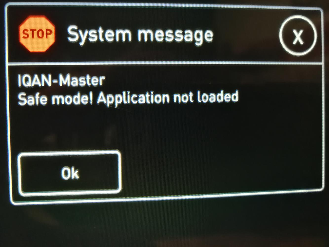
and it stays in this screen.
I've connected the Bat+ to 24V bat- to the ground and the RTC to the 24V with a 1.5K resistor.
is there any reason why this could happen?
Theleo De Bruyn

Hello, Please check if you have connected the Adress tag?
If you start-up IQAN MD4 display's without Adress tag , it will start up in safe mode

MC41 question
Hi there,
I have been working on the project that would involve MC41 master. Application that I have been working requires 8 digital outputs. MC41 has got 4 DOUTs and 2 bidirectional COUTs (current out). In the past I used XA2 that allowed to use these COUTs for DOUTs. It was clearly shown on electrical schematic. When I have checked electrical schematic for MC41 it did not show this option. Can I use these COUTs for additional DOUTs that I require or what can be suggested to achieve my requirement. I would like to add that I am rather 'mechanical' guy and have some problems with electronics. Have been working with IQAN since 2007.
Thanks in advance
Richard Kowalczyk
RKad Engineering
32 Kingussie Ave Castle Hill NSW 2154 Australia
☎: +61 2 98940750
📲 :+61 431 639 295
E: richard.kowalczyk@rkad.com.au

MC43 Errors in logs after key off
We noticed that we are getting the errors below in the MC43 log occasionally and it appears to get logged when turning machine off. Machine runs fine and no errors appear during running. I verified that the log has no errors during running, but when I key off and then key on and check MC43 log, the errors below are logged in MC43 log.
Any ideas as to why these errors would get logged on key off intermittently? Any suggestions as to resolve this?
Bus Length
I have an application that requires a total bus length of approx 150 Mtrs - The Instructioin book referred to in another post says the max length "between nodes" is 100 mtrs - So If I put an additional node to act as a booster - is that ok?

Any suggestion for wireless ICP canbus gateway?
Hi everyone,
There is someone who find a product able to communicate wireless between two master module (MC4x and a MD4) ?
I tried few without a good success in the past. They lost communication, the latency is too high and no one was able to do an update of the program.
So, I'm looking for a recommendation if there is any product able to replace a wire for a 200' distance.
Thanks you all!
Connect PC to MD3 by G1 modem
Hi all,
I connected an old G1 modem to a MD3.
The connection between them is OK, the modem receive and send SMS.
But when I connect my laptop with IQANRun2 to the system (MD3+G1) I have a Blue Screen.
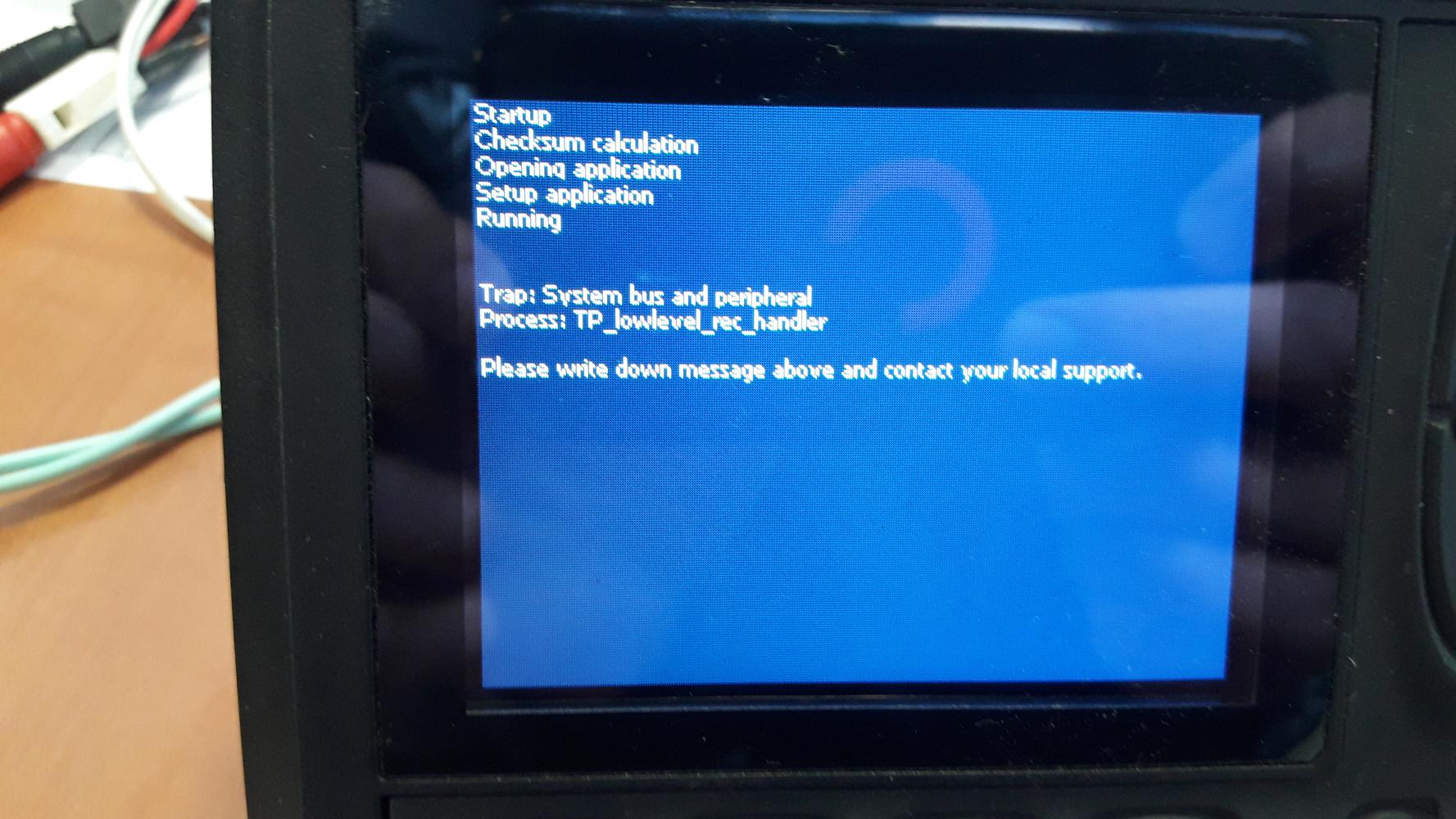
Do you think the modem I'm using can cause the problem if it send voice instead of data?(56k USB Modem USRobotics)
Resistive Fuel Sending Unit into MC43?
Quick question on fuel senders.
The kind we have included with our fuel tank is in fact not a current out, but resistive fuel sender. That is, 1 terminal is connected to ground and 1 terminal is the signal wire with varying resistance based on fuel level.
Is there any way that the MC43 can read this?

MC43 DOUT HS + LS
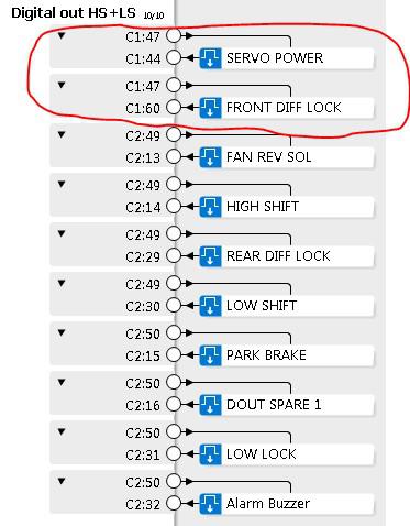
We are having some odd things happening with a system designed using DOUT HS + LS outputs.
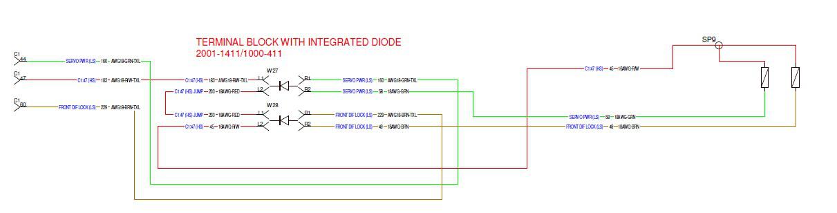
We will start with the first group circled in Red below, but are having the same issues with the other HS + LS groups. You can also reference the schematic below for the HS + LS wiring for “Servo Power” and Front “Diff Lock”. This is with "DOUT under current detection" on.
- If Servo Power and Front Diff Lock both are False and we disconnect one or the other, the corresponding function will show “open load” as expected.
- If Servo Power is True and Front Diff Lock is False, and we disconnect either one, the corresponding function will show “open load” as expected.
- If Servo Power is False and Front Diff Lock is True and we disconnect Servo Power, no “open load” is shown
- If Servo Power is False and Front Diff Lock is True and we disconnect Front Diff Lock, both show “open load”
- If Servo Power is True and Front Diff Lock is True and we disconnect either one, no “open load” is shown
If we turn "DOUT under current detection" off, the outputs will behave how we understand they are supposed to. Although, doing so removes open load detection when the output is true.
Using MC4x to drive Pulsar 75 hz coils (retrofit of coils)
The instruction book recommends NOT using an MC4x for 33/75 hz Pulsar coils.
I have an application where we are using an MC43 driving PF coils, and the customer is asking for a retrofit to 75hz pulsars, for common coils with other equipment. Is it possible to add external diodes/etc and drive these coils, or will we have to replace the controller?
Customer support service by UserEcho


