
 XC4x C1 Harness
Hello,
This is a small but frustrating nitpick.
The XC4x C1 Prototyping Harness (Parker no. 20085116) comes with wires installed in the C1:4 and C1:20 position.
This is annoying, because in order to use these modules, you need to install the ID Tag. (Parker no. 20085131 for example)
So every time you use this (expensive) part, you need to de-pin these two wires, remove them from the harness, and install the ID Tag.
Ideally there would be no wires present in these slots.
Like the older style XA2 Prototyping Harness (Parker no. 5030030).
Regards,

 l have an MC2 and want to replace ,what is the closest replacement

Actuating 24Vdc coil with MD4
Trying to actuate a 24Vdc coil for a skinner valve with the MD4. I know the MD4 only has LS digital outputs so I am wondering if we would need to use incorporate a voltage divider? I plan on using a relay for that coil as well.

Green line appeared on MD4
We have installed a brand new display in a battery powered rig this week. Its serial number starting with 2305 and production date of 230202.
It has been OK for a week but after the battery in the rig went flat, this line appeared:
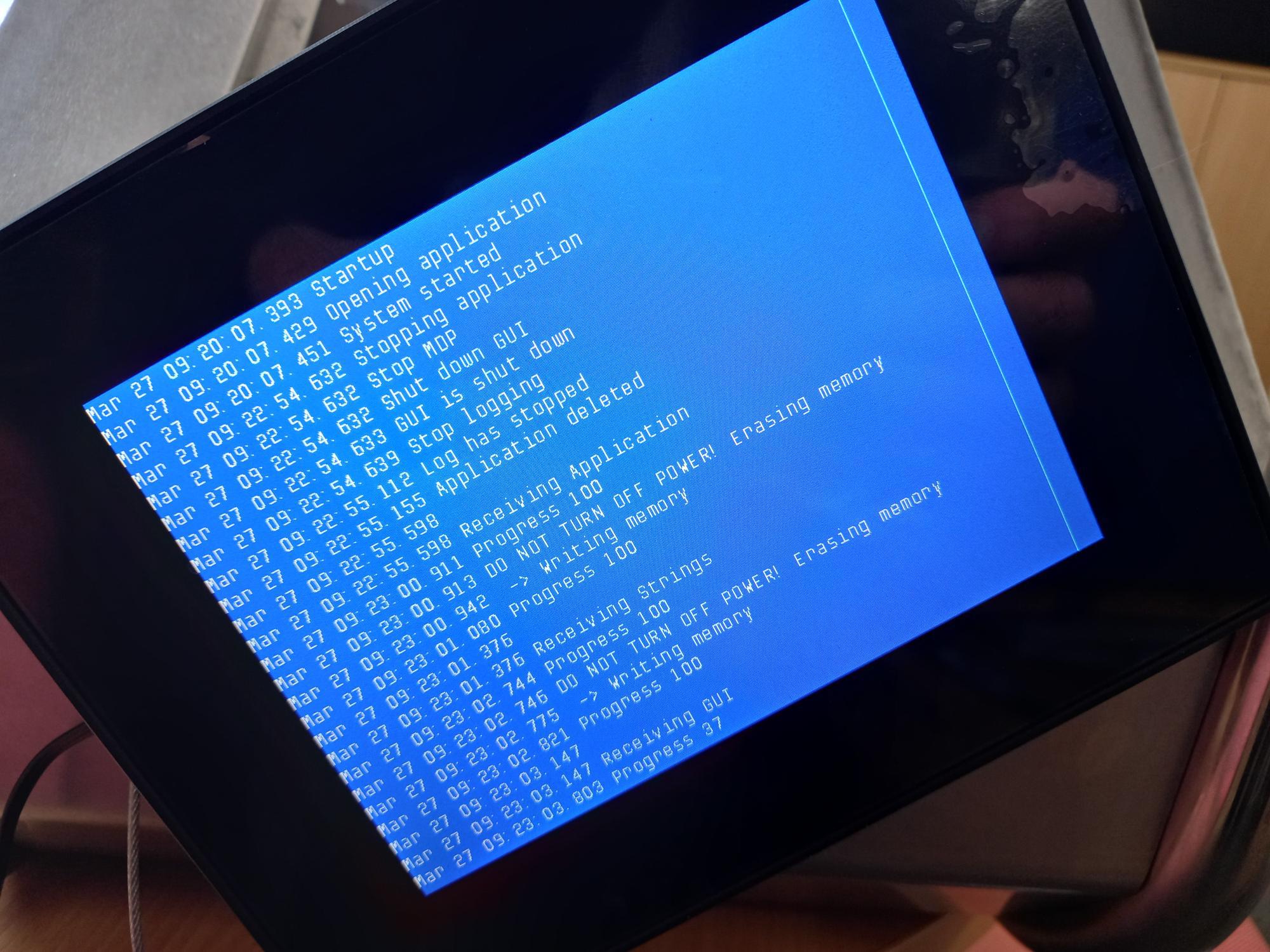
Only thing I can think of was the battery was depleted and resulted in the display flashing when the battery got to a level where it was unable to power the module. It performed OK after the battery was recharged but after a few hours the line appeared.
Anyone had this problem or similar before?

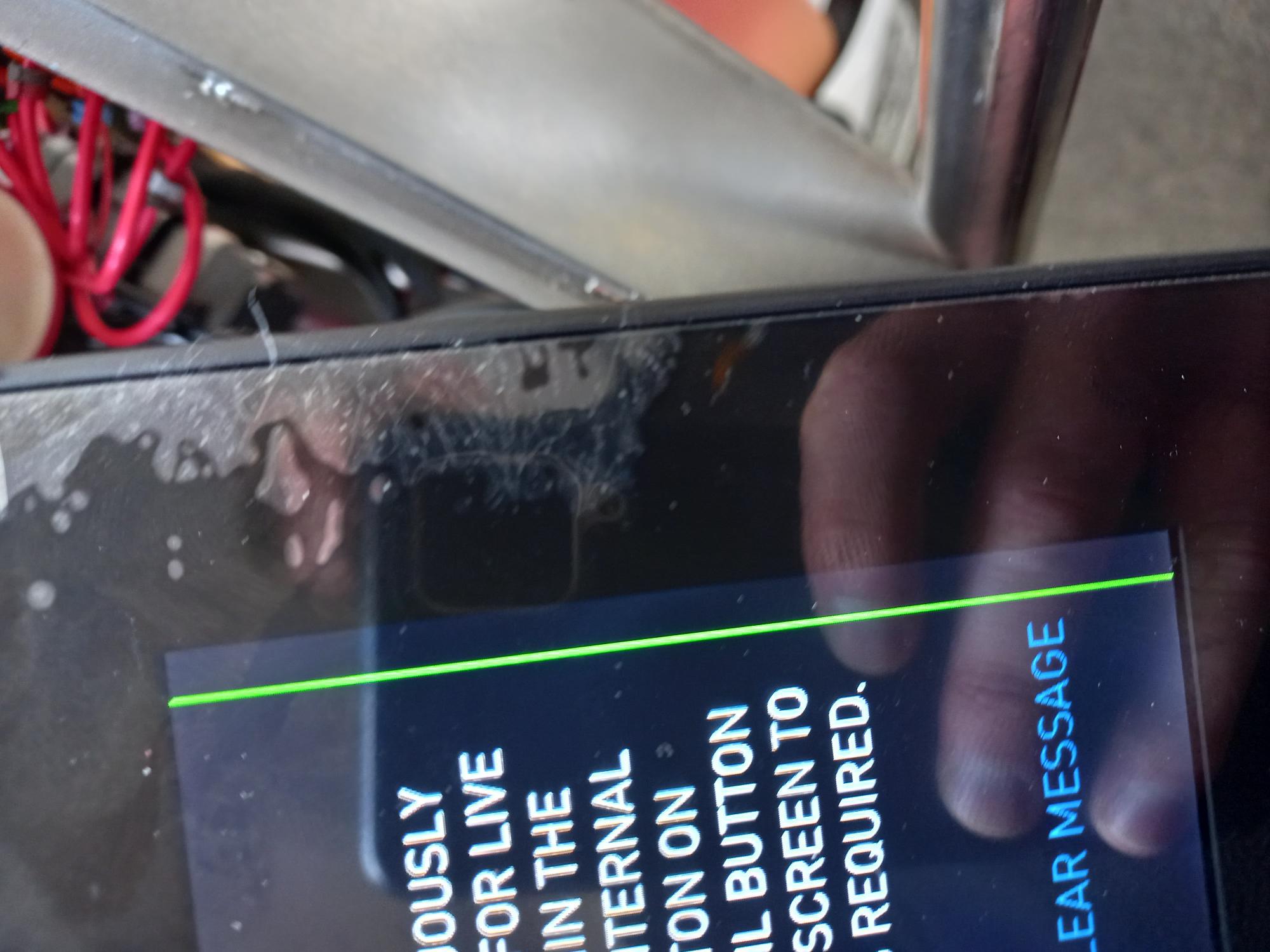
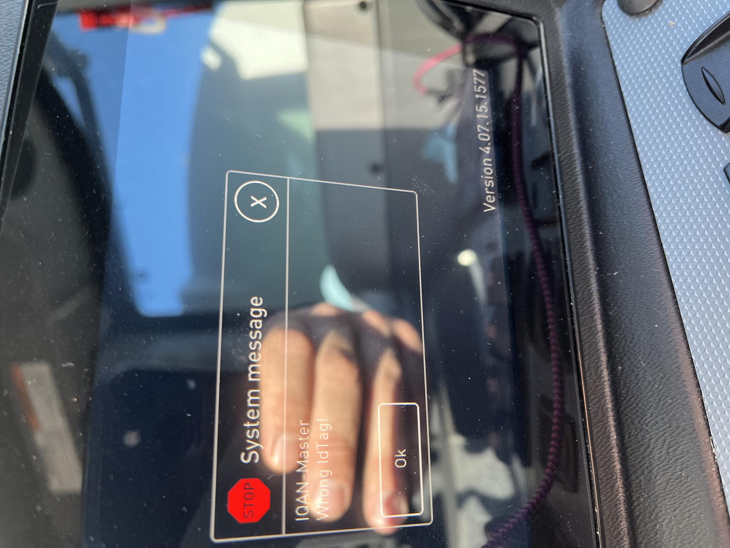
Wrong ID Tag on MD4 Start up
When powering on the MD4 the system message "IQAN-Master Wrong Id Tag!" appears on the screen. This does not happen every time the machine is powered on but is getting more frequent. Restarting or shutting off the power to the MD4 does not resolve the problem consistently. The screen remains black when this issue happens. Any help is greatly appreciated.

XC43 DOUT HS in parallel
When connecting loads to high side digital outputs in parallel, the manual says on page 96 "Increased drive capability
Power driver high-side is connected in parallel with adjacent output to drive double
load current." On page 116 it states the max load per output is 4 amps and max load per group is 6 amps. So when you connect in parallel is the max load 8 amps? Or 6 amps?

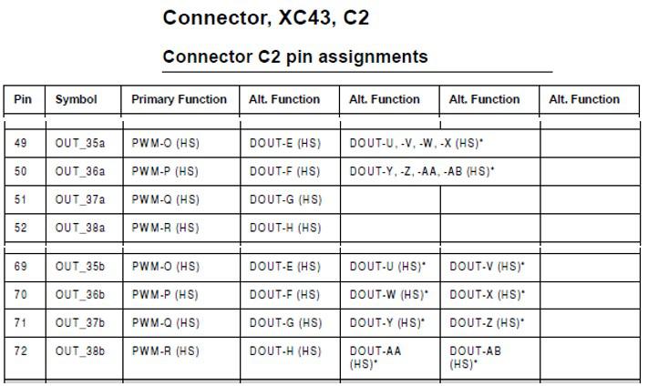
OUT pins a/b
Apologize that I have to use the wired topic. Otherwise the submit window will go to search result and not be able to submit my question.
Why there are OUT_xxa and OUT_xxb? Are there any relationship between them? Have to use them in pairs?

CAN bus critical error
I have issue regarding CAN bus critical error on the MD4,
can any one suggest me to reification above issue.
I am waiting for your valuable reply.

Obsolete MC1606
Good Afternoon, All,
I am working on an old Iqan transmission controller for a company that has since gone defunct.
Do any of the old timers around here know anything about an IQAN MC1606?
Does anyone know how I would go about cloning the project so that I can install it on another used module?
Any information on this obsolete controller would be appreciated.

Customer support service by UserEcho


