
 Electrical schematics
Good afternoon.
Some years ago there was available the electrical schematics such as for example IQAN-MD3_uk_electrical_schematic.
Are these still available as I am after a copy of both pdf and dwg for:
IQAN MD4 electrical schematic
IQAN MD4 electrical system schematic
IQAN XA2 electrical schematic
IQAN LC5 electrical schematic

Open Load status not resetting in all situations
I am having a problem with the open load detection on a COUT on am MC43FS
- I am running IQANdesign 5.03.14.5040
- The manual indicates that the output detects open load two different ways which may be true, but the controller responds in three different ways.
- When the output is off, if the load is disconnected, the controller will set the open load status to TRUE, when the load is reconnected, the controller will set the open load status to FALSE and allow normal operation.
- When the output is on and passing some normal current, if the load is disconnected the controller will set the open load status to TRUE and turn off the output, if the load is reconnected, the open load status remains FALSE, and the output remains off until the command is set to zero. Setting the command to zero causes the controller to reset the open load status to FALSE, after which the output will respond to a normal current command.
- When the output is on, AND some fault causes the resistance of the load to increase such that less than 50% of the commanded current can be pushed through the load, the controller will, set the open load status to TRUE and turn off the output. Unfortunately commanding the output to zero does not cause the controller to reset the open load status to FALSE. This acts like the open load status is latched to TRUE if it was tripped by “extreme saturation”
- It is my belief the third response is a bug in MC43FS because, a MC2 running IQANdesign 4.07.7.4605 works as expected I.E. commanding the current to zero would reset the open load status to FALSE Such that the controller could lower the current and try again.

More (HS)* (LS)* MC43FS
Hi,
I have a applciation with alots of safety control Dout.
Like i could read a the page 97 and 99 of the instruction book manuel of the MC43FS.
We can have 5 Dout.
In safety function we need to combine one HS and one LS pin to a output.
In Dout i have acces to 5 direcly and would need 6.
I would like to know if it is possible to use the pin C2:71 HS and combine with a other LS for example C2:16 ?
Else my other solution would be to use Cout as a ON/OFF signal output unidirectional.
Thanks
Dart

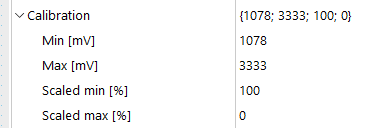
Scaling resistance to voltage
I am trying to calibrate a level sensor that has a resistance output of 240 ohms (empty) to 33 ohms (full). The calibration below was what the setup is currently, but I am getting a high error on the VIN input. I am looking to fix the min and max, but I am unsure of how to scale this to voltage. I am getting a raw value of ~4999 at full.
Using a resistance output sensor on MC43
A customer has purchased a resistance output level sensor (240-33 ohms). I have tried to find more information regarding converting this to a VIN, but couldn't find too much. I am wondering what else needs to be done other than incorporating a voltage divider in their circuit.


Ambient air temperature sender
I thought this would be easy to find but having no luck. I have a request to read the outside ambient temperature on the MD4-7 and not having any luck finding anything to do this with. If all else fails the standard ones I have used for hydraulic fluid might work in a pinch but unsure how accurate that would be. If this is something anyone has any ideas on I would appreciate any feedback.

XC43 Current Outputs Bounds for short and open load
Hello, I am working with an XC43 current output that controls a bidirectional valve and want to make sure I use the right resistor to avoid problems with getting short and open load errors. I have found the minimum resistance for my case is 20ohms based on Appendix A in Parker's Family instruction book, but I am not sure how to find the maximum. Any help would be appreciated.

firmware g12
i am starting to use the g12's for the first time. they freeze in the middle of uploads.
do you have ability for updates and how do you do it.
we probably bought about 20 of these
 system of mc43 to md4 wirelessly
i want to make a remote md4 to work with my system to access data. is there an easy way to have a remote that will connect tot an mc43 wirelessly. that way the user can get custom screens
Customer support service by UserEcho


