
 What wires in the m12 connector for the SV 120 camera do you use to connect to the MD5-8

MC42FS Error code R4:2 1:1:3 I/O startup test failed
Got the R4:2 1:1:3 I/O startup test failed error on a MC42FS module.
Even when I only put power (24v external power supply) and a address tag on it.
Tried to put an empty program on the controller. The controller is installing the program but when it restarts it keeps coming back with the same error.
Is there anything I can try to fix this?

XC43 multiple DOUT overloads
We are having a problem with XC43 giving overload errors in multiple DOUT's at the same time.
Construction of the application is MD4 + 2xMC43 + 3xXC43, running with IQANdesign 6.08.
Problem is only in one of those XC43's. We use those DOUT's to control two different kind of solenoids, connected as shown below:
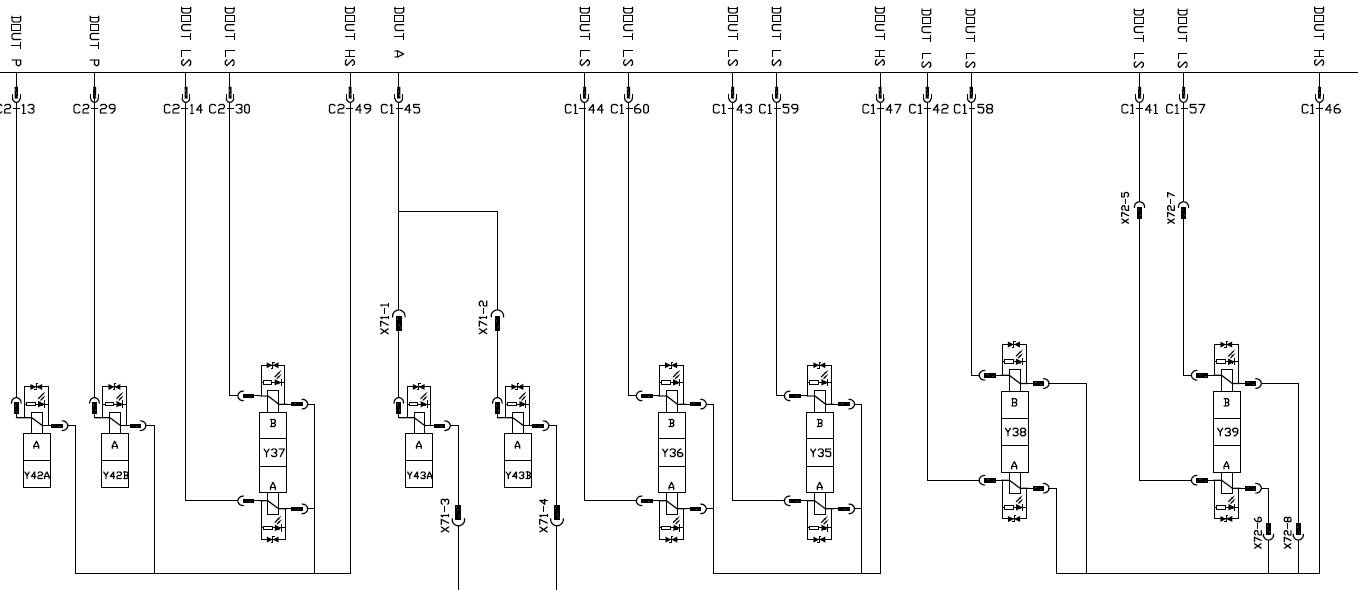
Fault codes are occurring only in:
- C2:29 (load 0,83 A), C2:13 (0,83 A), C2:30 (1,29 A) and C2:14 (1,29 A) overload simultaneously
- If you activate only one of these DOUT LS's, every one of those are giving fault code
- C1:58 (1,29 A) and C1:42 (1,29 A) overload simultaneously
- If you activate only one of these DOUT LS's, both of those are giving fault code
- C1:60 (1,29 A) and C1:44 (1,29 A) overload simultaneously
- If you activate only one of these DOUT LS's, both of those are giving fault code
Sometimes you can drive a day without having any fault codes, sometimes fault codes appear at the first activation at the morning. Even when the machine is standing still, only ignition on and you are activating those solenoids, it can be that you can activate those 50 times without problem and then suddenly the next activation gives you the fault codes.
We have replaced that XC43 with the other one installed in the same machine, still giving the fault codes. The original XC43 didn't give any fault codes when installed to another location. We have checked and measured all the wires, not shorted to the ground or to each others. Measured the coils, everyone has the correct resistance. Replaced all the diodes at the solenoids' connectors, no change. We have dozens of machines with exactly same construction and none of those are having the similar problem.
Any ideas how we should proceed with the troubleshooting? Thanks!

Molex Connector part numbers
Molex has indicated that the MX123 connector series are scheduled for end of life. These connectors are used on all of the MC4 and XC4 series modules. Does Parker have any information on potential future compatible replacement parts?

The supplier have decided to change part numbers on all of their harness connectors used in the MX123 connector family due to an improvement in Wire Dress Cover retention. The replacements have no change in form, fit or function.
This will affect following parts that we recommend using for IQAN-_C4_ family and also the IQAN-MD5 family:
Part numbers change:
IQAN-_C4_:
66-P connector 34822-0013 -> 216741-0001
73-P connector 34566-0103 -> 216739-0001
Dress cover 34565-0003 -> 34565-0005
IQAN-MD5:
56-P connector 34576-0703 -> 216742-0001
56-P connector 34576-1903 -> 216742-0007
Dress cover 34575-0003 -> 34575-0005
We will update our documentation to reflect this change.

MC2 Questions
The MC2 unit is now obsolete, but we still have units in the field that we need to support, the MC2 unit went through 2 part numbers in its life time as I can see, 20070899 - replaced in 2015 by 20077787.
What is the difference between these unit and if I found an old one for sale would I still be able to use utilize it?
Can the MC2 unit (20077787) still be purchased by special order if needed?
HS+LS output EMF capability
Would like to use the HS+LS configuration to control the HV contactors in an Hybrid configuration. I am reading note about using Diode to protect against EMF. But I cannot find specification on acceptable EMF level? Our contactors have built-in EMF clamping diode rated at 150V?
Also how does the open circuit detection in an off state works? injecting a current i am assuming. How much? Just want to avoid issue with Dropoff voltage for the coil.

Driving Pulsar with the PWM on MC43
Hi There,
Hope all is well,
Is there any possibility to drive Proportional 24v 33Hz Pulsar valves with the PWM outputs from a MC43 ? Reading the manual it states that this will not work from MC43,but reaching out to see if it is possible.
ATM I am using the proportional flow from the pump and making the Pulsar more like an ON/OFF, This is working currently but would like to use the Pulsar proportionally.
Thank you

Max bus length
What's the realistic max bus length of master and diagnostics? I have an application that requires 2 masters at approx 100m apart from one another. Can these have master and diagnostic bus at this length?
I recall seeing in the IQAN instruction manual 40m is the recommended but maximum is 100m. Is this length take into account the 40 twists per meter, as 40 twists per meter at 100m length between modules would mean cabling of in excess of 100m actual cable length? If IQAN bus works at 250kbs, does this follow standard bus protocols and have a theoretical max of 250m @ 250kbs?
Will the soon to be added HS busses help any limitation?
I can always add an additional node to act as a midpoint transferring the data from one bus to another, effectively reducing the max length of a master bus to 50m, however it would need a diagnostics bus shared between all the master modules, which would be the maximum distance of 100m, and therefore the limitation?
Would CAN routing help me here with a central node that just runs its own independent program and routes the diagnostic bus and master bus through, and therefore has its own application file separate from the main 2 node application file?

MC4x/XC4x 12V 30W solenoid overload error
What is the suggested solution for driving NG6 valves with standard 30W solenoids at 12V system voltage with MC4x/XC4x modules?
We use the HS+LS digital outputs for driving Parker D1VW valves with "K" code solenoids in a 12V system. As stated in the instrucion book, max load per output is 2.5A, but the measured current is 2.7A (as in the D1VW catalogue). The measured solenoid resistance is 5 Ohm, but it should be within 7-14 Ohm (MC4x/XC4x instrucion book).
30W solenoids are standard at other valve suppliers too, so changing the valve isn't an option. Change the system voltage to 24V also isn't possible for this project.
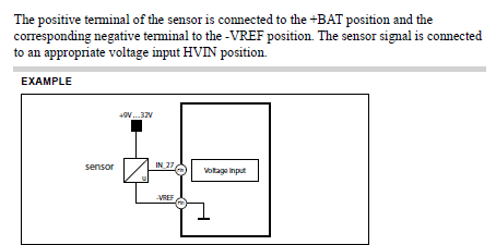
Max current on XC43 -VREF pins
We are providing some sensors with a 0V supply through the VREF circuit on XC43 module but cannot find the maximum current capacity of these pins. The manual states VREF has a limit of 150mA, but is this limitation on both the +ve side and -ve side?
I was under the impression -VREF is connected internally to the -BATT terminals, therefore does this mean there is a higher current limit? I cant find a value in the manual:
Customer support service by UserEcho